CRUISE CONTROL
2.0L
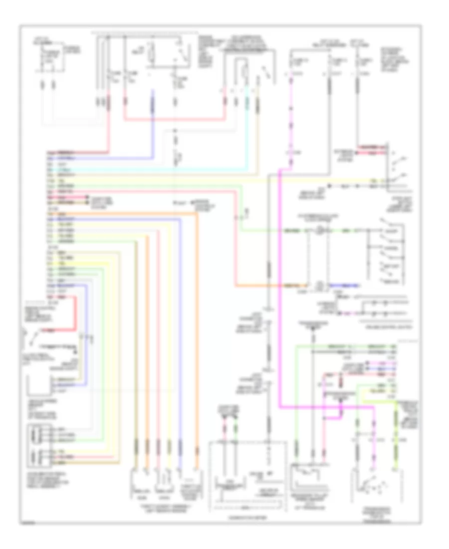
2.0L, Cruise Control Wiring Diagram for Mitsubishi Lancer GT 2012

List of elements for 2.0L, Cruise Control Wiring Diagram for Mitsubishi Lancer GT 2012:
- (in steering column) clock spring
- (main)
- (on underhood fuse/relay block) throttle actuator control motor relay
- (sub)
- 120a
- A-09
- A-10
- Accelerator pedal position sensor (top of accelerator pedal assembly)
- B-108
- B-109
- C-128
- C-204
- C-205
- C-304
- C-313
- C-317
- C-39
- C-40
- C-41
- Can transceiver circuit
- Cancel
- Circuit
- Clutch pedal position switch (m/t)
- Combination meter
- Computer data lines system
- Cpu
- Cruise control switch
- Cruise ind
- Engine compartment fuse/relay box (left side of engine compt)
- Engine control module (left rear of engine compt)
- Engine controls system
- Etacs-ecu (on rear of junction block, behind left end of dash)
- Exterior lights system
- Fuse 12 7.5a
- Fuse 15a
- Fuse 18 7.5a
- Fuse 2 15a
- Fuse 20a
- Fuse 7.5a
- Fusible link 36
- Fusible link box
- G13 (behind left side of dash)
- G16 (rear of engine compt)
- Hall ic
- Hot at all times
- Hot w/ ig1 relay energized
- Interior lights system
- Joint connector c-03 (behind left side of dash)
- Led drive
- Mfi relay
- On/off
- Pnk
- Red
- Res/acc
- Secondary pulley speed sensor (cvt) (at transaxle)
- Set/cst
- Stoplight switch (under left side of dash)
- Throttle actuator control motor
- Throttle body assembly (left rear of engine)
- Transaxle control module (cvt) (behind left side of dash)
- Transmission range switch (top of transmission)
- Transmissions system
- Vehicle speed sensor (m/t) (on right side of transaxle)
2.0L TURBO
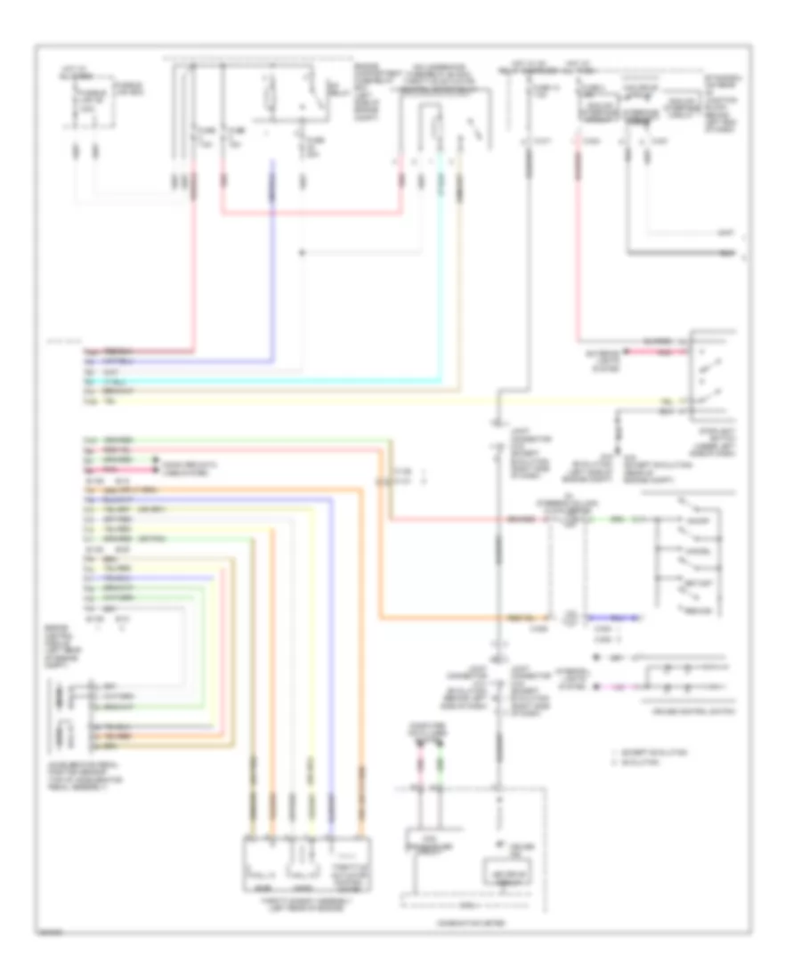
2.0L Turbo, Cruise Control Wiring Diagram (1 of 2) for Mitsubishi Lancer GT 2012
List of elements for 2.0L Turbo, Cruise Control Wiring Diagram (1 of 2) for Mitsubishi Lancer GT 2012:
- (in steering column) clock spring
- (main)
- (on underhood fuse/relay block) throttle actuator control motor relay
- (or pnk)
- (sub)
- 120a
- Accelerator pedal position sensor (top of accelerator pedal assembly)
- Analog interface circuit
- B-09
- B-10
- B-108
- B-109
- C-128
- C-131
- C-202
- C-204
- C-205
- C-301
- C-304
- C-317
- Can drive circuit
- Can transceiver circuit
- Cancel
- Circuit
- Combination meter
- Computer data lines system
- Cpu
- Cruise control switch
- Cruise ind
- Engine compartment fuse/relay box (left side of engine compt)
- Engine control module (left rear of engine compt)
- Etacs-ecu (on rear of junction block, behind left end of dash)
- Evolution
- Except evolution
- Exterior lights system
- Fuse 12 7.5a
- Fuse 15a
- Fuse 2 15a
- Fuse 20a
- Fuse 7.5a
- Fusible link 36
- Fusible link box
- G16 (except evolution) (rear of engine compt)
- G19 (evolution) (left side of engine compt)
- Hall ic
- Hot at all times
- Hot w/ ig1 relay energized
- Interface circuit
- Interior lights system
- Joint connector c-01 (evolution) (behind left side of dash)
- Joint connector c-03 (except evolution) (right side of dash)
- Led drive
- Mfi relay
- On/off
- Pnk
- Red
- Res/acc
- Set/cst
- Stoplight switch (under left side of dash)
- Throttle actuator control motor
- Throttle body assembly (left rear of engine)
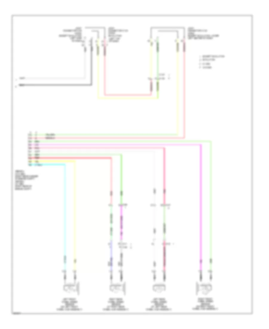
2.0L Turbo, Cruise Control Wiring Diagram (2 of 2) for Mitsubishi Lancer GT 2012
List of elements for 2.0L Turbo, Cruise Control Wiring Diagram (2 of 2) for Mitsubishi Lancer GT 2012:
- (evolution)
- (left top of dash)
- (or red)
- Abs-ecu (w/o asc) (right rear corner of engine compt) asc-ecu (w/ asc) (right rear of engine compt)
- C-127
- C-130
- C-45
- C-47
- C-56
- D-11
- D-15
- Evolution
- Except evolution
- Joint connector c-05 (can2) (except evolution) (left side of dash)
- Joint connector c-104 (can2)
- Joint connector c-124 (can3) (except evolution: lower left center of dash)
- Left front wheel speed sensor (on left front wheel hub assembly)
- Left rear wheel speed sensor (at left rear wheel hub assembly)
- Nca
- Pnk
- Red
- Right front wheel speed sensor (on right front wheel hub assembly)
- Right rear wheel speed sensor (at right rear wheel hub assembly)
- W/ asc
- W/o asc
2.4L
2.4L, Cruise Control Wiring Diagram for Mitsubishi Lancer GT 2012
List of elements for 2.4L, Cruise Control Wiring Diagram for Mitsubishi Lancer GT 2012:
- (in steering column) clock spring
- (main)
- (on underhood fuse/relay block) throttle actuator control motor relay
- (sub)
- 120a
- A-09
- A-10
- Accelerator pedal position sensor (top of accelerator pedal assembly)
- B-108
- B-109
- C-128
- C-204
- C-205
- C-304
- C-313
- C-317
- C-39
- C-40
- C-41
- Can transceiver circuit
- Cancel
- Circuit
- Clutch pedal position switch (m/t)
- Combination meter
- Computer data lines system
- Cpu
- Cruise control switch
- Cruise ind
- Engine compartment fuse/relay box (left side of engine compt)
- Engine control module (left rear of engine compt)
- Engine controls system
- Etacs-ecu (on rear of junction block, behind left end of dash)
- Exterior lights system
- Fuse 12 7.5a
- Fuse 15a
- Fuse 18 7.5a
- Fuse 2 15a
- Fuse 20a
- Fuse 7.5a
- Fusible link 36
- Fusible link box
- G13 (behind left side of dash)
- G16 (rear of engine compt)
- Hall ic
- Hot at all times
- Hot w/ ig1 relay energized
- Interior lights system
- Joint connector c-03 (behind left side of dash)
- Led drive
- Mfi relay
- On/off
- Pnk
- Red
- Res/acc
- Secondary pulley speed sensor (cvt) (at transaxle)
- Set/cst
- Stoplight switch (under left side of dash)
- Throttle actuator control motor
- Throttle body assembly (left rear of engine)
- Transaxle control module (cvt) (behind left side of dash)
- Transmission range switch (top of transmission)
- Transmissions system
- Vehicle speed sensor (m/t) (on right side of transaxle)