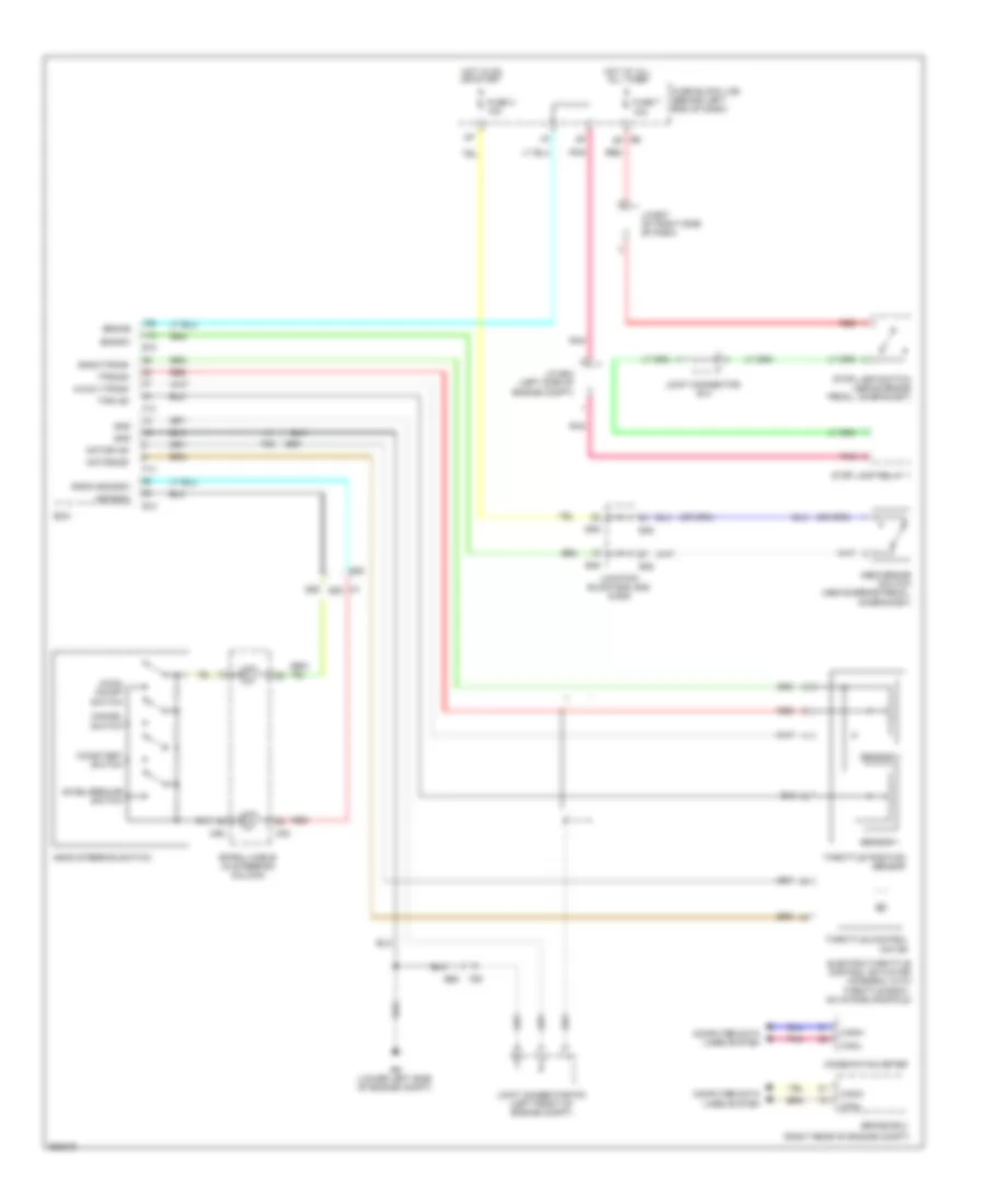
CRUISE CONTROL
Cruise Control Wiring Diagram, Except Hybrid for Nissan Altima Hybrid 2011

List of elements for Cruise Control Wiring Diagram, Except Hybrid for Nissan Altima Hybrid 2011:
- (2.5l)
- (2.5l) primary speed sensor
- (3.5l)
- (a/t)
- (above brake pedal, on bracket)
- (left front of engine compt) (2.5l) j/c f02 (3.5l) j/c f05
- (left front of engine compt) j/c f03
- (m/t)
- (or red)
- 10a
- 2.5l
- 2.5l california
- 2.5l except california
- 3.5l
- 55g
- 58g
- A/t
- Accel/resume switch
- Accelerator pedal position sensor
- Aps1
- Aps2
- Ascd brake switch (above brake pedal, on bracket)
- Ascd clutch switch
- Ascd steering switch
- Ascdsw
- Avcc1-aps1
- Avcc1-tps-b1
- Avcc2-aps2
- Bncsw
- Brake
- Can-h
- Can-l
- Cancel switch
- Coast/set switch
- Combination meter
- Computer data lines system
- Cruise ind
- Cvt unit (3.5l)
- Display)
- E10
- E11
- E30
- E31
- E32
- E44
- E45
- E46
- E6 8p
- E9 (lower left side of engine compt)
- Ecm (left front of engine compt)
- Electric throttle control actuator (2.5l: integral with throttle body, on intake manifold) (3.5l: integral with throttle body)
- F10
- F13
- F14
- F78
- F79
- F90
- F91
- Fuse
- Fuse 3 10a
- Fuse 7 10a
- Fuse block (j/b) (behind left end of dash)
- Gnd
- Gnda-aps1
- Gnda-aps2
- Gnda-ascdsw
- Gnda-tps-b1
- Hot at all all times
- Hot in on or start
- Hot w/ ignition relay 1 energized
- Intelligent power distribution module engine room (ipdm e/r) (left side of engine compt)
- J/c e07
- J/c e14
- Joint connector e06 (behind left end of dash)
- Joint connector f04 (3.5l) joint connector f01 (2.5l) (left front of engine compt)
- Junction block e44, e45 & e46
- M/t
- M30
- M88
- Main on/off switch
- Motor1-b1
- Motor2-b1
- Pnk
- Pri spd sens
- Primary speed sensor
- Red
- Sec spd
- Secondary speed sensor (on transaxle)
- Sens
- Sens gnd
- Sens pwr
- Sensor 1
- Sensor 2
- Shield
- Spiral cable (in steering column)
- Stop lamp relay 1 (a/t)
- Stop lamp switch
- Tcm (left front of engine compt)
- Throttle control motor
- Throttle position sensor
- Tps1-b1
- Tps2-b1
- Unified meter control unit (w/ information
- Vign
Cruise Control Wiring Diagram, Hybrid for Nissan Altima Hybrid 2011
List of elements for Cruise Control Wiring Diagram, Hybrid for Nissan Altima Hybrid 2011:
- (main) on/off switch
- (right rear of engine compt)
- 55g
- 58g
- Accel/resume switch
- Ascd brake switch (above brake pedal, on bracket)
- Ascd steering switch
- Ascdsw
- Avcc1-tps-b1
- Bncsw
- Brake
- Brake ecu
- Can-h
- Can-l
- Cancel switch
- Coast/set switch
- Combination meter
- Computer data lines system
- E10
- E30
- E45
- E46
- E48
- E6 8p
- E68
- E9 (lower left side of engine compt)
- Ecm
- Electric throttle control actuator (integral with throttle body, on intake manifold)
- F13
- F14
- F80
- Fuse 3 10a
- Fuse 7 10a
- Fuse block (j/b) (behind left end of dash)
- Gnd
- Gnda-ascdsw
- Gnda-tps-b1
- Hot at all all times
- Hot in on or start
- J/c e04 (left side of engine compt)
- J/c e07 (at right side of dash)
- Joint connector e14
- Joint connector f03 (left front of engine compt)
- Junction block e45, e46 & e48
- M30
- M88
- Motor1-b1
- Motor2-b1
- Pnk
- Red
- Sensor 1
- Sensor 2
- Spiral cable (in steering column)
- Stop lamp relay 1
- Stop lamp switch (above brake pedal, on bracket)
- Throttle control motor
- Throttle position sensor
- Tps1-b1
- Tps2-b1