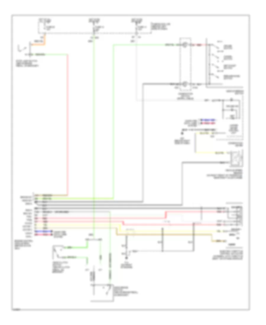
CRUISE CONTROL
Cruise Control Wiring Diagram for Nissan Altima SE-R 2006
List of elements for Cruise Control Wiring Diagram for Nissan Altima SE-R 2006:
- A/t
- Ascd brake switch (above brake pedal, on bracket)
- Ascd clutch switch (above clutch pedal, on bracket)
- Ascd steering switch
- Ascd sw
- Avcc2
- Bnc sw
- Brake sw
- Can-h
- Can-l
- Cancel switch
- Close
- Combination meter
- Combination switch (spiral cable)
- Computer data lines system
- Cruise ind
- Cruise switch
- E30
- Electric throttle control actuator (integral with throttle body, on intake manifold)
- Engine control module (ecm) (behind glove box)
- F14 (on front of engine)
- Fuse 12 10a
- Fuse 14 10a
- Fuse 20 10a
- Fuse block (j/b) (behind left side of dash)
- Gnd-a
- Hot at all all times
- Hot in on or start
- M/t
- M102
- M24
- M30
- M57 (behind right side of dash)
- Motor 1
- Motor 2
- Open
- Pnk
- Red
- Resume/accel switch
- Sensor 1
- Sensor 2
- Set ind
- Set/coast switch
- Stop lamp switch (above brake pedal, on bracket)
- Tps1
- Tps2
- Unified meter control unit
- Vehicle speed sensor (on right front of transaxle, near right axle flange)
 English