CRUISE CONTROL
Cruise Control Wiring Diagram, Coupe for Nissan Altima SV 2013

List of elements for Cruise Control Wiring Diagram, Coupe for Nissan Altima SV 2013:
- (left front of engine compt) j/c f02
- (left side of engine compt) j/c e07
- (on transaxle) primary speed sensor
- (or red)
- 10a
- 15a
- 55g
- 58g
- Accel/resume switch
- Accelerator pedal position sensor (on accelerator pedal assembly)
- Aps1
- Aps2
- Ascd brake switch (above brake pedal, on bracket)
- Ascd steering switch
- Ascdsw
- Avcc1-aps1
- Avcc1-tps-b1
- Avcc2-aps2
- Bncsw
- Brake
- California
- Can-h
- Can-l
- Cancel switch
- Coast/set switch
- Combination meter
- Computer data lines system
- Cruise ind
- Display)
- E10
- E11
- E15 (lower left side of engine compt)
- E18
- E30
- E31
- E44
- E45
- E46
- E6 8p
- E9 (lower left side of engine compt)
- Ecm (left front of engine compt)
- Ecm relay
- Electric throttle control actuator (integral w/ throttle body, on intake manifold)
- Except california
- F10
- F13
- F14
- F90
- F91
- Fuse
- Fuse 3 10a
- Fuse 7 10a
- Fuse block (j/b) (behind left end of dash)
- Gnd
- Gnda-aps1
- Gnda-aps2
- Gnda-ascdsw
- Gnda-tps-b1
- Hot at all times
- Hot in on or start
- Hot w/ ignition relay 1 energized
- Ipdm e/r (intelligent power distribution module engine room) (left side of engine compt)
- J/c e14 (left side of engine compt)
- J/c e44 & e45 e45 (except cali- fornia)
- J/c f01 (left front of engine compt)
- J/c f03 (left front of engine compt)
- Junction block e44, e45 & e46
- M30
- M88
- Main on/off switch
- Motor1-b1
- Motor2-b1
- Motrly-b1
- Output speed sensor
- Pnk
- Pri spd sens
- Red
- Sec spd
- Sens
- Sens gnd
- Sensor 1
- Sensor 2
- Shield
- Spiral cable (in steering column)
- Ssof
- Stop lamp relay 1 (in fuse & fusible link box)
- Stop lamp switch (above brake pedal, on bracket)
- Tcm (left front of engine compt)
- Throttle control motor
- Throttle control motor relay
- Throttle position sensor
- Tps1-b1
- Tps2-b1
- Unified meter control unit (w/ information
- Vbr
- Vign
- Vmot-b1
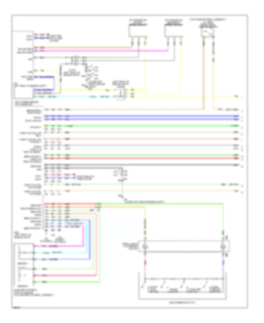
Cruise Control Wiring Diagram, Sedan (1 of 2) for Nissan Altima SV 2013
List of elements for Cruise Control Wiring Diagram, Sedan (1 of 2) for Nissan Altima SV 2013:
- (left front of engine compt) j/c f02
- (on transaxle) primary speed sensor
- (on transaxle) secondary speed sensor
- (or pnk)
- (or red)
- (or tan)
- (top of brake pedal assembly) (w/ ascd) brake pedal position switch
- 2.5l
- 2.5l california
- 2.5l except california
- 3.5l
- 42g
- 43g
- Accel/ resume switch
- Accelerator pedal position sensor (on accelerator pedal assembly)
- Apps1
- Apps2
- Ascd steering sw
- Ascd steering switch
- Brake pedal position sw
- Can-h
- Can-l
- Cancel switch
- Coast/set switch
- Compt) e15
- Computer data lines system
- E10
- E23
- E30
- E31
- E32
- E9 (lower left side of engine compt)
- Ecm (left front of engine compt)
- F13
- F14
- F25
- F78
- F90
- F91
- Gnd
- Ign sw
- Input spd
- Input speed sensor (on transaxle)
- J/c f03 (left front of engine compt)
- M30
- M88
- On/off (main) switch
- Pnk
- Pri spd sens
- Pwr splt
- Red
- Sec spd sens
- Sens
- Sens gnd
- Sens pwr sply
- Sensor 1
- Sensor 2
- Shield
- Spiral cable (in steering column)
- Stop lamp sw
- Tan
- Tcm (left front of engine compt)
- Throttle ctrl mtr (close)
- Throttle ctrl mtr (open)
- Throttle ctrl mtr pwr sply
- Throttle ctrl mtr rely
- Throttle position sens 1
- Throttle position sens 2
- Vign
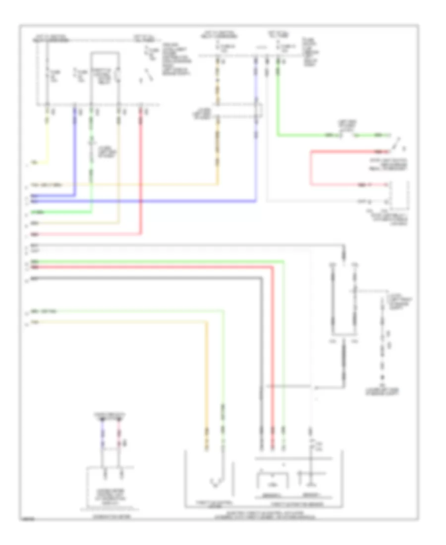
Cruise Control Wiring Diagram, Sedan (2 of 2) for Nissan Altima SV 2013
List of elements for Cruise Control Wiring Diagram, Sedan (2 of 2) for Nissan Altima SV 2013:
- (left end of dash) j/c e10
- (or shield)
- (or tan)
- 10a
- 15a
- 2.5l
- 3.5l
- Can-h
- Can-l
- Combination meter
- Computer data lines system
- E18
- E23
- E63
- E9 (lower left side of engine compt)
- Electric throttle control actuator (integral with throttle body, on intake manifold)
- F25
- F83
- F84
- Fuse
- Fuse 10 10a
- Fuse 30 10a
- Fuse block (j/b) (behind left end of dash)
- Hot at all all times
- Hot w/ ignition relay 1 energized
- Hot w/ ignition relay 2 energized
- Ipdm e/r (intelligent power distribution module engine room) (left side of engine compt)
- J/c e08 (left end of dash)
- J/c f01 (left front of engine compt)
- M24
- Pnk
- Red
- Sensor 1
- Sensor 2
- Shield
- Stop lamp relay 1 (in fuse & fusible link box)
- Stop light switch (above brake pedal, on bracket)
- Tan
- Throttle control motor
- Throttle control motor relay
- Throttle position sensor
- Unified meter control unit (w/ information display)