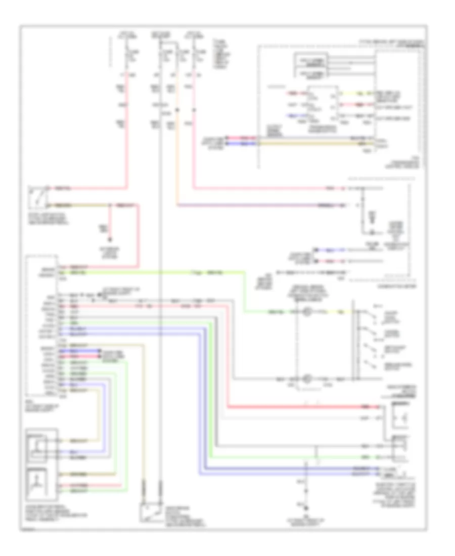
CRUISE CONTROL
Cruise Control Wiring Diagram for Nissan Armada SL 2012
List of elements for Cruise Control Wiring Diagram for Nissan Armada SL 2012:
- (armada: behind left side of dash) combination switch (spiral cable)
- (at right front of engine compt) e9
- (titan: behind left side of dash) a/t assembly
- 13p
- 15g m31
- 18g
- 19g
- 46g
- Accelerator pedal position (app) sensor (titan: at top of accelerator pedal assembly)
- Aps1
- Aps2
- Ascd brake switch (if equipped) (titan: on bracket, above brake pedal)
- Ascd steering switch (if equipped)
- Ascdsw
- Avcc
- Avcc2
- Bncsw
- Brake
- C1 (vin)
- C2 (vout)
- C3 (gnd) f506
- Can-h
- Can-l
- Cancel switch
- Close
- Combination meter
- Computer data lines system
- Cruise ind
- E152
- E16
- E9 (at right front of engine compt)
- Ecm (at right side of engine compt)
- Electric throttle control actuator (armada: at top left side of engine) (titan: at left front of engine compt)
- Exterior lights system
- F14
- F502
- F503
- F505
- F54
- Fuse 10a
- Fuse block (j/b) (behind right end of dash)
- Gnd
- Gnd-a
- Gnd-a2
- Hot at all times
- Hot in on or start
- Input speed sensor 1
- Input speed sensor 2
- M102
- M24
- M30
- M31
- M60
- M61 (behind center of dash)
- Motor 1
- Motor 2
- On/off (main) switch
- Open
- Out spd sen gnd
- Out spd sen vout
- Output speed sensor
- Pnk
- Red
- Resume/accel switch
- Rev sen vin (or out spd sens pwr)
- Sensor 1
- Sensor 2
- Set ind
- Set/coast switch
- Stop lamp switch (titan: on bracket, above brake pedal)
- Tcm (transmission control module)
- Tps1
- Tps2
- Transmission range switch
- Unified meter control unit (w/ information display)
For engine performance wiring diagrams, see ENGINE PERFORMANCE WIRING DIAGRAMS article.
For additional transmission wiring diagrams, see TRANSMISSION WIRING DIAGRAMS article.
 Русский