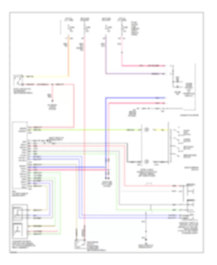
CRUISE CONTROL
Cruise Control Wiring Diagram for Nissan Armada Titanium 2010
List of elements for Cruise Control Wiring Diagram for Nissan Armada Titanium 2010:
- (right front of engine compt) e9
- 13p
- Accelerator pedal position (app) sensor (at top of accelerator pedal assembly)
- Aps1
- Aps2
- Ascd brake switch (if equipped) (on bracket, above brake pedal)
- Ascd steering switch
- Ascdsw
- Avcc
- Avcc2
- Bncsw
- Brake
- Can-h
- Can-l
- Cancel switch
- Close
- Combination meter
- Computer data lines system
- Cruise ind
- E16
- E9 (right front of engine compt)
- Ecm (at right side of engine compt)
- Electric throttle control actuator (armada: at top left side of engine) (titan: at left front of engine compt)
- Exterior lights system
- F54
- Fuse 10a
- Fuse block (j/b) (behind right end of dash)
- Gnd
- Gnd-a
- Gnd-a2
- Hot at all times
- Hot in on or start
- M102
- M24
- M30
- M60
- M61 (behind center of dash)
- Motor 1
- Motor 2
- On/off main switch
- Open
- Pnk
- Red
- Resume/accel switch
- Sensor 1
- Sensor 2
- Set ind
- Set/coast switch
- Spiral cable (combination switch) (armada: behind left side of dash)
- Stop lamp switch (on bracket, above brake pedal)
- Tps1
- Tps2
- Unified meter control unit (w/ information display)
 English