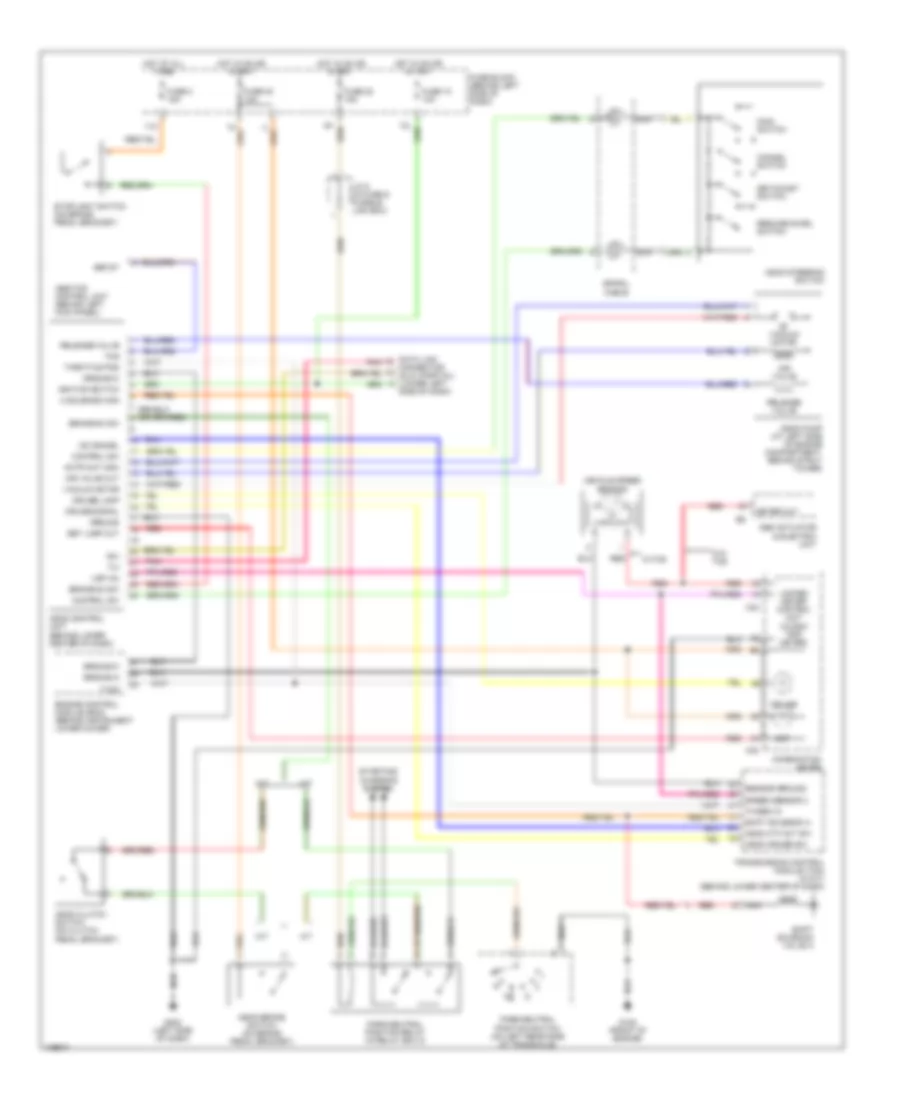
CRUISE CONTROL
Cruise Control Wiring Diagram for Nissan Maxima GLE 2001
List of elements for Cruise Control Wiring Diagram for Nissan Maxima GLE 2001:
- 11k
- A solenoid mon
- A/t
- Abs actuator & electric unit
- Abs/tcs control unit (behind left kick panel)
- Actr out high
- Air valve
- Air valve out
- Ascd 4th cut sw
- Ascd brake switch (on brake pedal bracket)
- Ascd clutch switch (on clutch pedal bracket)
- Ascd control unit (behind lower center of dash)
- Ascd cruise sw
- Ascd pump (at left side of engine compartment, behind strut tower)
- Ascd steering switch
- Asr st
- Brake nc sw
- Brake no sw
- Cancel switch
- Combination meter
- Control sw
- Cruise
- Cruise lamp
- Cruise signal
- Data link connector (dlc) (partial) (lower left
- Engine control module (ecm) (behind instrument lower cover)
- Fuse 10 10a
- Fuse 2 15a
- Fuse 20 15a
- Fuse 30 10a
- Fuse block (behind left side of dash)
- G125 (front of engine)
- G202 (left side of dash)
- Ground
- Ground-a
- Ground-c
- Hot at all times
- Hot in on or start
- Ignition switch
- J/c 8 (in fuse & fusible link box)
- M/t
- M33
- M34
- Main switch
- Meter out
- Nca
- Od cancel
- Park/neutral position relay (in relay box 2)
- Park/neutral position switch (on left rear side of transaxle)
- Pnk
- Red
- Release valve
- Resume/accel switch
- Rxi
- Sensor ground
- Set
- Set lamp out
- Set/coast switch
- Shift solenoid a
- Shift solenoid valve a
- Side of dash)
- Speed sensor 2
- Spiral cable
- Starting/ charging system
- Stoplight switch (on brake pedal bracket)
- Tcs
- Th/sen in
- Throttle pos
- Transmission control module (tcm) (w/a/t) (behind lower center of dash)
- Tvo0
- Txi
- Unified meter control unit (w/odo/ trip meter)
- Vacuum motor
- Vehicle speed sensor
- Vsp (in)
- W/o tcs
- W/tcs
 English