CRUISE CONTROL
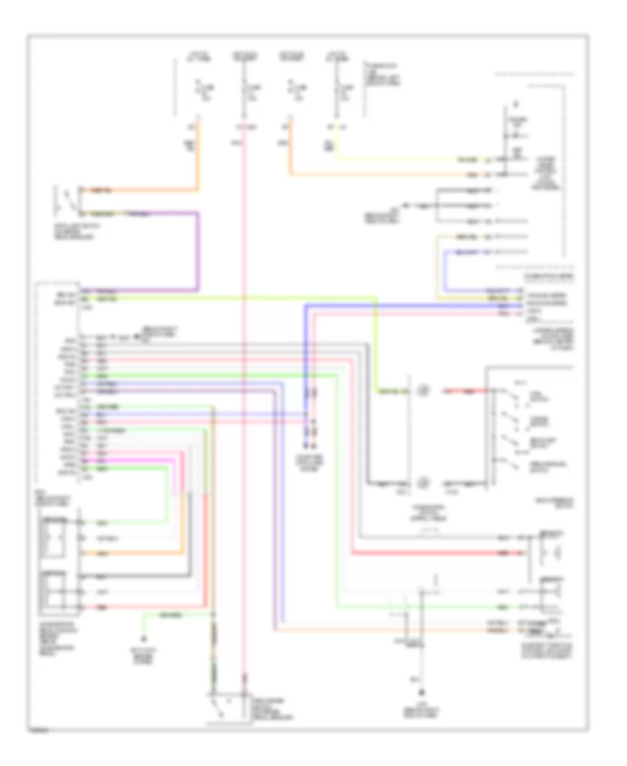
Cruise Control Wiring Diagram for Nissan Maxima SL 2007
List of elements for Cruise Control Wiring Diagram for Nissan Maxima SL 2007:
- (behind right side of dash) m61
- 1q e30
- Accelerator pedal position sensor (above accelerator pedal)
- Anti-lock brakes system
- Aps1
- Aps2
- Ascd brake switch (on brake pedal bracket)
- Ascd steering switch
- Ascd sw
- Avcc
- Avcc2
- Bnc sw
- Brk sw
- Can-h
- Can-l
- Cancel switch
- Close
- Combination meter
- Combination switch (spiral cable)
- Computer data lines system
- Cruise ind
- Ecm (behind right side of dash)
- Electric throttle control actuator (on throttle body)
- F54
- Fuse 10a
- Fuse block (j/b) (behind left side of dash)
- Gnd
- Gnd-a
- Gnd-a2
- Hot at all times
- Hot in on or start
- M102
- M30
- M57 (behind right side of dash)
- M79 (behind right end of dash)
- M82
- Main switch
- Motor 1
- Motor 2
- Nca
- Open
- Pnk
- Red
- Resume/accel switch
- Rx(comb meter)
- Sensor 1
- Sensor 2
- Set ind
- Set/coast switch
- Stop lamp switch (on brake pedal bracket)
- Tps1
- Tps2
- Tx(comb meter)
- Unified meter & a/c amplifier (behind center of dash)
- Unified meter control unit (w/odo/ trip meter)
 English