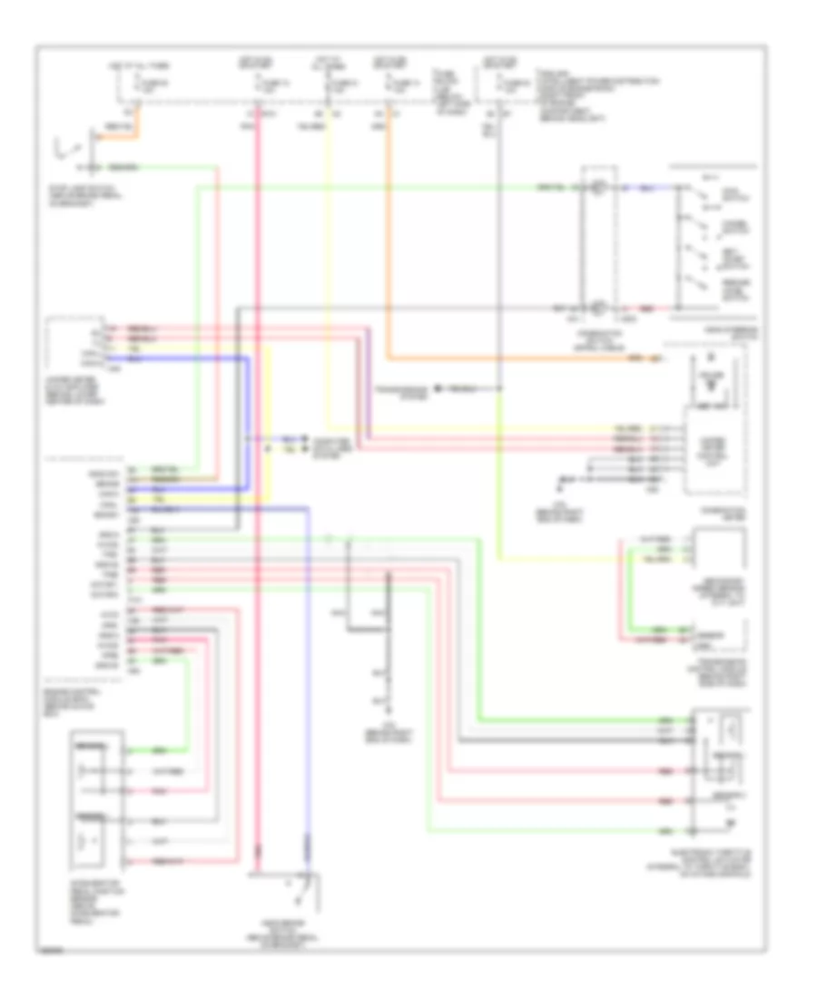
CRUISE CONTROL
Cruise Control Wiring Diagram for Nissan Murano S 2007
List of elements for Cruise Control Wiring Diagram for Nissan Murano S 2007:
- Accelerator pedal position sensor (above accelerator pedal)
- Aps1
- Aps2
- Ascd brake switch (above brake pedal, on bracket)
- Ascd steering switch
- Ascd sw
- Avcc
- Avcc2
- Bncsw
- Brake
- Can-h
- Can-l
- Cancel switch
- Combination meter
- Combination switch (spiral cable)
- Computer data lines system
- Cruise ind
- E101 1c
- Electronic throttle control actuator (integral to throttle body, on intake manifold)
- Engine control module (ecm) (behind glove box)
- F101
- Fuse 12 10a
- Fuse 14 10a
- Fuse 20 10a
- Fuse 21 10a
- Fuse 83 10a
- Fuse block (j/b) (below left side of dash)
- Gnd
- Gnd-a
- Gnd-a2
- Gns-a
- Hot at all times
- Hot in on or start
- Ipdm e/r (intelligent power distribution module engine room) (right front of engine compartment, behind headlight)
- M203
- M25
- M31
- M49
- M78 (behind right end of dash)
- M80
- Main switch
- Motor 1
- Motor 2
- Nca
- Pnk
- Red
- Resume/ accel switch
- Secondary speed sensor (integral to cvt unit)
- Sensor
- Sensor 1
- Sensor 2
- Set ind
- Set/ coast switch
- Stop lamp switch (above brake pedal, on bracket)
- Tps1
- Tps2
- Transmission control module (behind right side of dash)
- Transmissions system
- Unified meter & a/c amplifier (behind lower center of dash)
- Unified meter control unit
 English