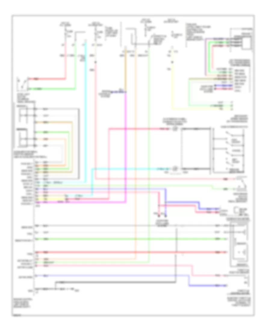
CRUISE CONTROL
Cruise Control Wiring Diagram for Nissan Murano SL 2011
List of elements for Cruise Control Wiring Diagram for Nissan Murano SL 2011:
- (in steering wheel) combination switch (spiral cable)
- (on transmission) tcm (transmission control module)
- Accelerator pedal position sensor (above accelerator pedal)
- Acsd steering switch
- Aps1
- Aps2
- Ascd brake switch (on brake pedal bracket)
- Ascd sw
- Brk sw
- Can-h
- Can-l
- Cancel
- Combination meter
- Computer data lines system
- Cruise ind & set ind
- Cvt unit
- E10
- E103
- E105
- E16
- E38
- Electric throttle control actuator (integral to throttle body)
- Engine control module (ecm) (left side of engine compt)
- Engine controls system
- F12
- Fuse 10a
- Fuse 43 10a
- Fuse 51 15a
- Fuse block j/b (left end of dash)
- Gnd
- Hot at all times
- Hot in on or start
- Ipdm e/r (intelligent power distribution module engine room) (left side of engine compt)
- M11
- M303
- M33
- Main (on/off)
- Motor close
- Motor open
- Motor relay
- Nca
- Pnk
- Pri sens
- Primary
- Pwr sply
- Red
- Resume/ accelerate
- Sec sens
- Secondary
- Sen gnd
- Sens gnd
- Sens pwr
- Sens pwr sply
- Sensor 1
- Sensor 2
- Set/ coast
- Speed sensor
- Speed sensor (on transmission)
- Stop light switch (on brake pedal bracket)
- Stop lp
- Throttle control motor
- Throttle control motor relay
- Throttle position sensor
- Tps1
- Tps2
 English