CRUISE CONTROL
Cruise Control Wiring Diagram (1 of 2) for Nissan NV200 Taxi 2014

List of elements for Cruise Control Wiring Diagram (1 of 2) for Nissan NV200 Taxi 2014:
- (left rear of engine compt) e24
- (or red)
- 27b
- 33b
- 38a
- 39a
- 50a
- 92a
- Accel/res switch
- Accelerator pedal position sensor (top of accelerator pedal assembly)
- Apps1
- Apps2
- Ascd brake switch
- Ascd steering sw
- Ascd steering switch (if equipped)
- Brake pedal position switch (w/ ascd) (top of brake pedal assembly)
- Can-h
- Can-l
- Cancel switch
- Coast/ set switch
- Computer data lines system
- E16
- E43
- Ecm (left rear of engine compt)
- Ecm gnd
- Electric throttle control actuator (on throttle body assembly)
- F10
- F11
- Fuse 10 10a
- Fuse 11 10a
- Fuse 15a
- Fuse 3 10a
- Fuse block (j/b) (lower left end of dash)
- Hot at all times
- Hot in on or start
- Hot w/ ignition relay energized
- Ign
- Ipdm e/r (intelligent power distribution module engine room) (left rear of engine compt)
- J/c e01 (center rear of engine compt)
- J/c f01 (left side of engine compt)
- M30
- M69
- M69 e7
- M88
- On/off (main) switch
- Pnk
- Red
- Sens gnd
- Sens pwr sply
- Sensor 1
- Sensor 2
- Shield
- Spiral cable (combination switch) (in steering column)
- Stop lamp switch (top of brake pedal assembly)
- Stp lmp sw
- Throttle control motor
- Throttle ctrl mtr (close)
- Throttle ctrl mtr (open)
- Throttle ctrl mtr pwr sply
- Throttle ctrl mtr rly
- Throttle position sensor
- Tps1
- Tps2
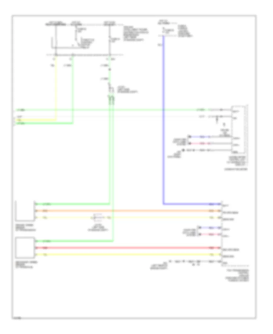
Cruise Control Wiring Diagram (2 of 2) for Nissan NV200 Taxi 2014
List of elements for Cruise Control Wiring Diagram (2 of 2) for Nissan NV200 Taxi 2014:
- Batt
- Can h
- Can l
- Can-h
- Can-l
- Combination meter
- Computer data lines system
- Cruise ind (w/ ascd)
- E41 (left rear of engine compt)
- E43
- Fuse & fusible link box (forward of battery)
- Fuse 23 10a
- Fuse 43 10a
- Fuse 52 15a
- Gnd
- Hot at all times
- Hot in on or start
- Hot w/ ecm relay energized
- Ign
- Ipdm e/r (intelligent power distribution module engine room) (left rear of engine compt)
- J/c f01 (left side of engine compt)
- M57 (right kick panel)
- Pnk
- Pri spd sens
- Primary speed sensor (in transmission)
- Red
- Sec spd sens
- Secondary speed sensor (in transaxle)
- Sens gnd
- Tcm (transmission control module) (forward of fuse & fusible link box)
- Throttle control motor relay
- Unified meter control unit (w/ information display)