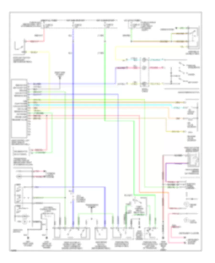
CRUISE CONTROL
Cruise Control Wiring Diagram for Nissan Quest GLE 1999
List of elements for Cruise Control Wiring Diagram for Nissan Quest GLE 1999:
- (in fuse & fusible link box) j/c 4
- (right side of dash) g201
- Air valve
- Air valve solenoid
- Ascd actuator (right side of engine compt)
- Ascd brake switch (on bracket, above brake pedal)
- Ascd control unit (right side of driver's footwell)
- Ascd hold relay (on relay box, left front corner of engine compartment)
- Ascd main switch
- Ascd steering switch
- Brake nc sw
- Brake no sw
- Cancel
- Cruise ind.
- Cruise lamp
- Cruise switch
- Electric speed- ometer
- Fuse & fusible link box (left front of engine compt)
- Fuse 22 20a
- Fuse 29 10a
- Fuse 30 10a
- Fuse 42 15a
- G100 (front of left front fender)
- G201 (right side of dash)
- G206 (center rear of dash)
- Ground
- Horn relay (on relay box)
- Horns system
- Hot at all times
- Hot at all times fuse block (behind dash, left of steering column)
- Hot in on or start
- Illum- ination
- Instrument cluster
- Instrument cluster system
- Interior lights system
- J/c 4 (in fuse & fusible link box)
- Main switch
- Od cancel
- Od cut signal
- Off
- Park/neutral position relay (on relay box)
- Park/neutral position switch (left side of transaxle)
- Pnk
- Pump power
- Release valve
- Release valve solenoid
- Res/acc sw
- Resume/ accelerate
- Set/coast
- Set/coast sw
- Spiral cable
- Stoplight switch (on bracket, above brake pedal)
- Theft warning relay (relay box)
- Transmission control module (behind dash, right of steering column)
- Transmission system
- Vacuum motor
- Vehicle speed sensor (on transaxle)
- Vss
- W/ theft
- W/o theft
 English