CRUISE CONTROL
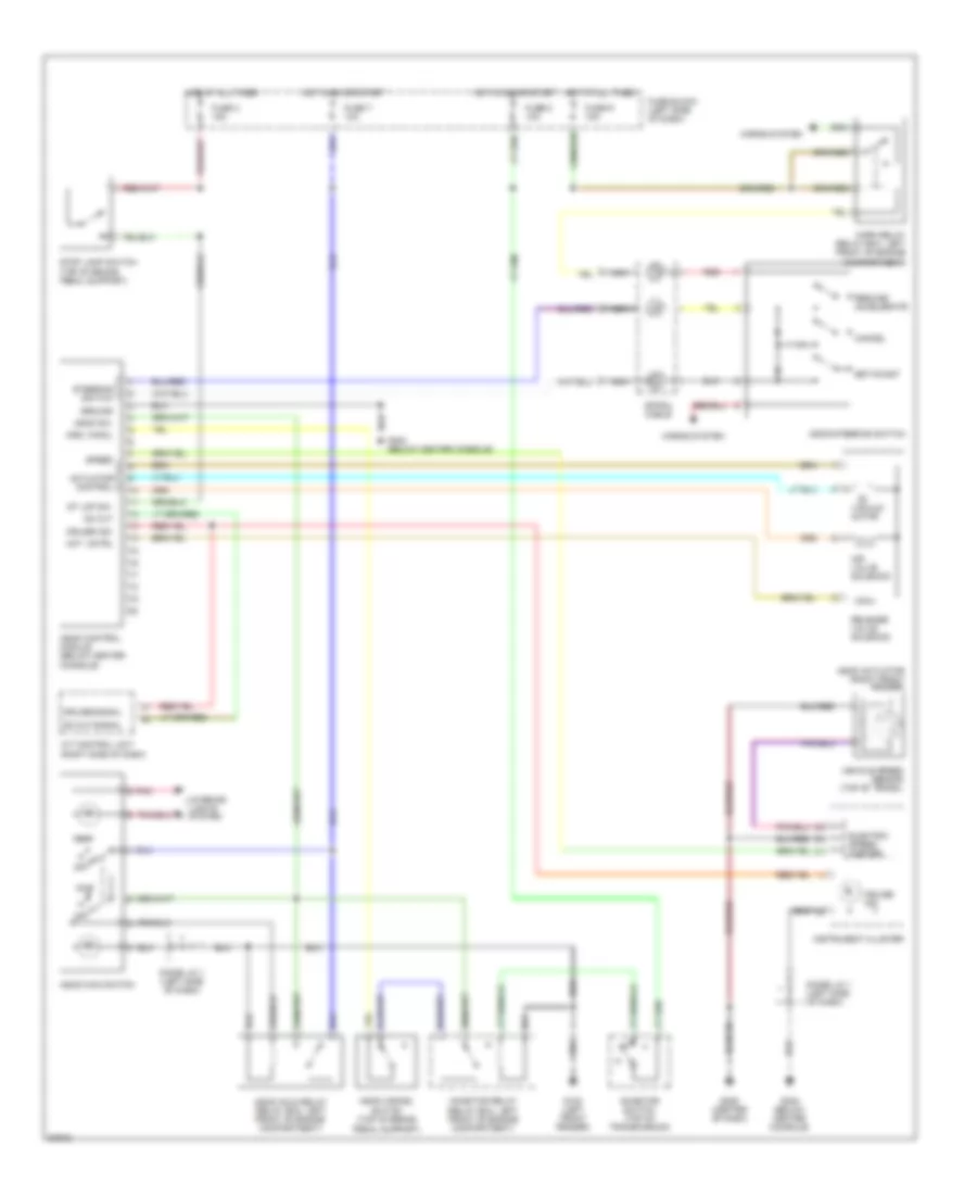
Cruise Control Wiring Diagram for Nissan Quest GXE 1994
List of elements for Cruise Control Wiring Diagram for Nissan Quest GXE 1994:
- A/t control unit (right side of dash)
- Act. cntrl
- Actuator control
- Air valve solenoid
- Ascd actuator (right front fender)
- Ascd cancel switch (top of brake
- Ascd control module (below center
- Ascd hold relay (relay box, left front of engine compartment)
- Ascd main switch
- Ascd steering switch
- Ascd sw.
- Cancel
- Console)
- Crs. cancl
- Cruise ind.
- Cruise signal
- Diode j/c 1 (left side of dash)
- Electric speed- ometer
- Fuse block (left side of dash)
- Fuse r 15a
- Fuse t 10a
- Fuse x 15a
- Fuse z 10a
- G100 (left front fender)
- G206 (center of dash)
- G302 (below center console)
- Ground
- Horn relay (relay box, left front of engine compartment)
- Horns system
- Hot at all times
- Hot at all times hot in on or start
- Hot in on or start
- Inhibitor relay (relay box, left front of engine compartment)
- Inhibitor switch (top of transmission)
- Instrument cluster
- Interior lights system
- Nca
- Od cut
- Od cut signal
- Off
- Pedal support)
- Pnk
- Red
- Release valve solenoid
- Resume/ accelerate
- Set/coast
- Speed
- Spiral cable
- St lmp sw.
- Steering switch
- Stop lamp switch (top of brake pedal support)
- Vacuum motor
- Vehicle speed sensor (top of trans.)
 English