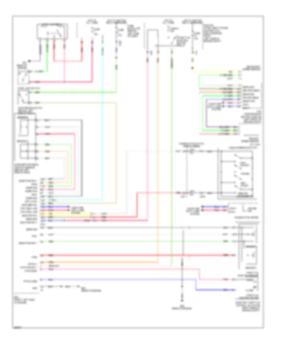
CRUISE CONTROL
Cruise Control Wiring Diagram for Nissan Quest SL 2014
List of elements for Cruise Control Wiring Diagram for Nissan Quest SL 2014:
- Accelerator pedal position sensor (behind left side of dash)
- Acsd steering switch
- Aps1
- Aps2
- Ascd brake switch (behind left side of dash)
- Ascd brk sw
- Ascd str sw
- Can comm line
- Can-h
- Can-l
- Cancel
- Close
- Combination meter
- Combination switch (spiral cable)
- Computer data lines system
- Cruise ind
- Cvt unit
- E10
- E103
- E105
- E16
- E21 (rear of engine)
- E38 (rear of engine)
- Ecm (front left side of engine)
- Ecm pwr sply
- Electric throttle control actuator (right rear of engine compt)
- F12
- Fuse 10a
- Fuse 51 15a
- Fuse block (j/b) (behind left side of dash)
- Gnd
- Hot at all times
- Hot w/ ignition relay energized
- Ipdm e/r (intelligent power distribution module engine room) (left side of engine compt)
- M11
- M303
- M33
- Main (on/off)
- Mtr (close)
- Mtr (open)
- Mtr pwr sply
- Mtr rly
- Nca
- Open
- Pnk
- Pri spd sens
- Primary speed sensor
- Red
- Resume/ accelerate
- Sec spd sens
- Secondary speed sensor
- Sens gnd
- Sens pwr
- Sens pwr sply
- Sensor 1
- Sensor 2
- Set/ coast
- Snsr gnd
- Snsr pwr
- Snsr pwr sply
- Stop lamp relay
- Stop lamp switch
- Stp lp sw
- Tcm (transmission control module) (left front of engine compt)
- Throttle control motor
- Throttle control motor relay
- Throttle position sensor
- Tps1
- Tps2
 English