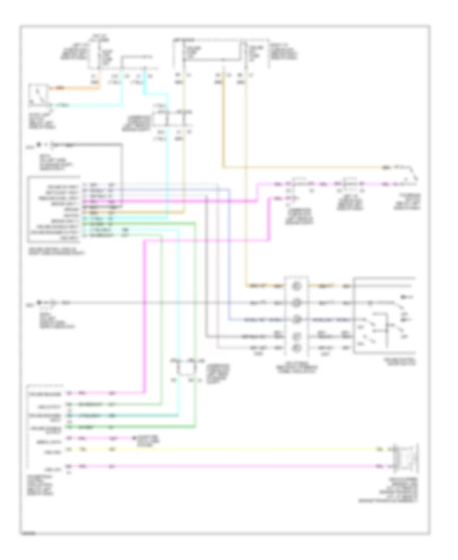
CRUISE CONTROL
Cruise Control Wiring Diagram for Pontiac Grand Am SE 2005
List of elements for Cruise Control Wiring Diagram for Pontiac Grand Am SE 2005:
- A12
- B12
- B4 c1
- Brake input 1
- Brake input 2
- C206
- C207
- Computer data lines system
- Cruise control module (right side of engine compt)
- Cruise control on/off switch
- Cruise disable input
- Cruise disable output
- Cruise engaged input
- Cruise engaged output
- Cruise fuse 10a
- Cruise on input
- Cruise release
- Cruise sw fuse 2a
- F12
- G101
- G201
- Ground
- Hot at all times
- Hot in run
- Ignition
- Inflatable restraint steering wheel module coil
- Left i/p fuse block (behind left side of dash)
- Off
- Powertrain control module (pcm) (below left side of dash)
- R/a
- Resume/accel input
- Right i/p fuse block (behind right side of dash)
- S/c
- Serial data
- Set/coast input
- Sp101 (on left side of engine compt, near strut)
- Sp201 (on left side of dash, near fuse block)
- Stop lamp switch (below left side of dash)
- Stop lps fuse 20a
- Tcc/brake switch (below left side of dash)
- Underhood fuse block (left rear of engine compt)
- Vehicle speed sensor (vss) (m/t: at rear of engine/transaxle) (a/t: at rear of engine/transaxle assembly)
- Vss high
- Vss input
- Vss low
- Vss output
 Русский