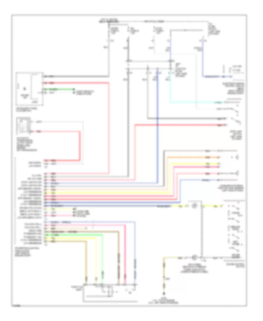
CRUISE CONTROL
Cruise Control Wiring Diagram for Pontiac Vibe 2010
List of elements for Cruise Control Wiring Diagram for Pontiac Vibe 2010:
- (or red)
- 5 volt reference
- Accelerator pedal position (app) sensor (left side of dash)
- App sensor 1 signal
- App sensor 2 signal
- Automatic transmission output shaft speed (oss) sensor (on transmission)
- Cancel
- Computer data lines system
- Cruise control switch
- Cruise ctrl sw sig
- Cruise ind
- Cruise on/off
- Drain wire
- Electronic brake control module (ebcm) (right side of engine compt)
- G105 (1.8l: top of engine) (2.4l: left rear of engine)
- High signal
- Hot at all times
- Hot w/ ig2 pcb relay energized
- I/p fuse block (left end of dash)
- Ign fuse 30 7.5a
- Ign voltage
- Inflatable restraint steering wheel module coil (under steering wheel)
- Instrument panel cluster (ipc)
- J236
- Left i/p junction block (left side of dash)
- Logic
- Low reference
- Low signal
- Low spd serial data
- Meter fuse 31 7.5a
- Mil ctrl
- Pnk
- Powertrain control module (pcm) (left side of engine compt)
- Red
- Resume/ accel
- Serial data bus (+)
- Serial data bus (-)
- Set/ coast
- Stop fuse 9 10a
- Stop lamp sw sig
- Stop lamp switch (left side of dash)
- Tac mtr ctrl 1
- Tac mtr ctrl 2
- Throttle body
- Tp sensor 1 sig
- Tp sensor 2 sig
- W/ vsc
- W/o vsc
- X12
 Русский