CRUISE CONTROL
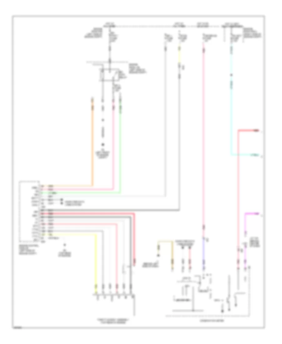
Cruise Control Wiring Diagram, Except Hybrid (1 of 2) for Toyota Camry Hybrid XLE 2013

List of elements for Cruise Control Wiring Diagram, Except Hybrid (1 of 2) for Toyota Camry Hybrid XLE 2013:
Cruise Control Wiring Diagram, Except Hybrid (2 of 2) for Toyota Camry Hybrid XLE 2013
List of elements for Cruise Control Wiring Diagram, Except Hybrid (2 of 2) for Toyota Camry Hybrid XLE 2013:
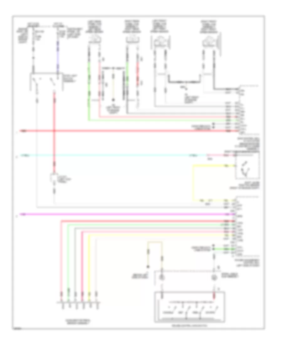
Cruise Control Wiring Diagram, Hybrid (1 of 2) for Toyota Camry Hybrid XLE 2013
List of elements for Cruise Control Wiring Diagram, Hybrid (1 of 2) for Toyota Camry Hybrid XLE 2013:
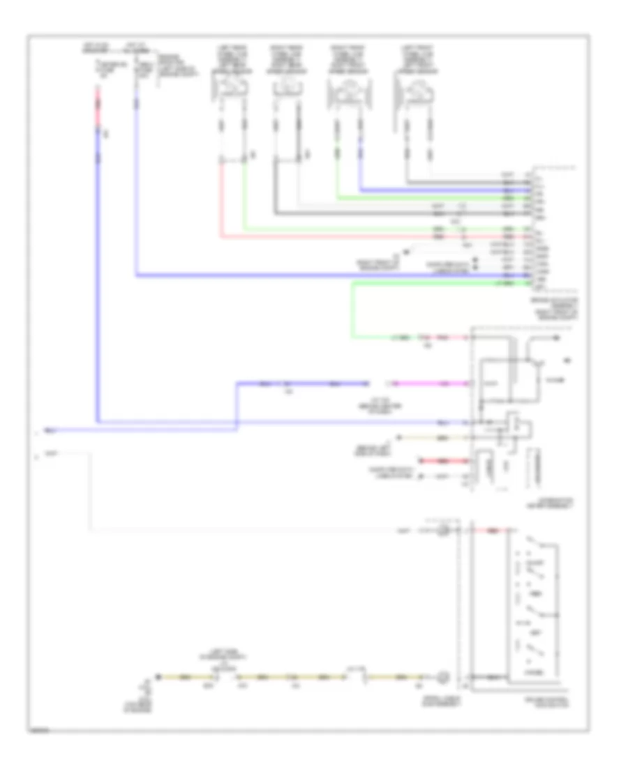
Cruise Control Wiring Diagram, Hybrid (2 of 2) for Toyota Camry Hybrid XLE 2013
List of elements for Cruise Control Wiring Diagram, Hybrid (2 of 2) for Toyota Camry Hybrid XLE 2013: