CRUISE CONTROL
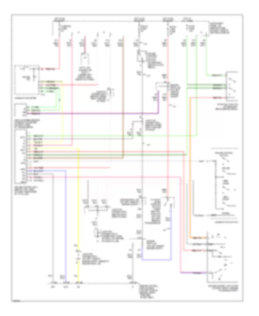
Cruise Control Wiring Diagram, GT-S for Toyota Celica GT 2004

List of elements for Cruise Control Wiring Diagram, GT-S for Toyota Celica GT 2004:
- A/t
- A/t indicator switch (park/ neutral position switch) (a/t) (on left rear of transmission)
- Acc
- Accelerator pedal position sensor (on accelerator pedal assembly)
- Batt
- Bk/up lamp fuse 5a
- C12
- C17
- C18
- C19
- C20
- Cancel
- Ccs
- Combination meter
- Combination switch
- Cruise
- Cruise control clutch switch (m/t) (on bracket, above clutch pedal)
- Cruise control switch
- Cruise ind
- E10
- E12
- Eb (at right front fender)
- Ec (at left side of cylinder head)
- Ecc
- Ecu-ig fuse 5a
- Efi 1 fuse 10a
- Efi fuse 20a
- Efi relay
- Engine control module (ecm) (on left side of engine compt, forward of battery)
- Engine room j/b (on left side of engine compt)
- Epa
- Epa2
- F12
- Ge01
- Hot at all times
- Hot in on or start
- I10
- Ig+
- Ignition switch
- Instrument panel j/b (behind panel on right side of center console)
- Junction connector 1 (on left side of engine compt, forward of battery)
- Junction connector 6 (behind upper left center of dash)
- Lock
- M/t
- M11
- Mrel
- Nca
- Off
- Res/ accel
- Set/ coast
- Spd
- St1-
- Start
- Stop fuse 10a
- Stoplight switch (on bracket, above brake pedal)
- Stp
- Throttle position sensor (on throttle body assembly)
- Vcp2
- Vcpa
- Vehicle speed sensor (combination meter) (on right side of transmission)
- Vpa
- Vpa2
- Vta
- Vta2
- Warning fuse 5a
Cruise Control Wiring Diagram, GT for Toyota Celica GT 2004
List of elements for Cruise Control Wiring Diagram, GT for Toyota Celica GT 2004:
- A/t
- A/t shift lever position switch (park/ neutral position switch) (on left rear of transmission)
- Bk/up lamp fuse 5a
- C12
- C17
- C18
- C19
- C20
- Cancel
- Ccs
- Combination meter
- Combination switch
- Cruise
- Cruise control actuator (in right front corner of engine compt)
- Cruise control clutch switch (on bracket, above clutch pedal)
- Cruise control ecu (behind left side of dash, near base of "a" pillar)
- Cruise control switch
- Cruise ind
- Data link connector (dlc) 3 (under left side of dash, near kick panel)
- Ecc
- Ect
- Ecu-ig fuse 5a
- Engine control module (ecm) (on left side of engine compt, forward of battery)
- Engine room j/b (on left side of engine compt)
- F10
- F14
- Gnd
- Hot at all times
- Hot in on or start
- I10
- Idl
- Idlo
- Ig+
- Instrument panel j/b (behind panel on right side of center console)
- Junction connector 10 (under right side of dash, on center of door pillar)
- Junction connector 2 (on left side of engine compt, beneath engine room j/b)
- Junction connector 8 (behind upper right center of dash)
- Junction connector 9 (behind right side of dash)
- K10
- M/t
- M11
- Od1
- Res/ accel
- Set/ coast
- Spd
- Stop fuse 10a
- Stoplight switch (on bracket, above brake pedal)
- Stp-
- Vehicle speed sensor (combination meter) (on right side of transmission)
- Warning fuse 5a