CRUISE CONTROL
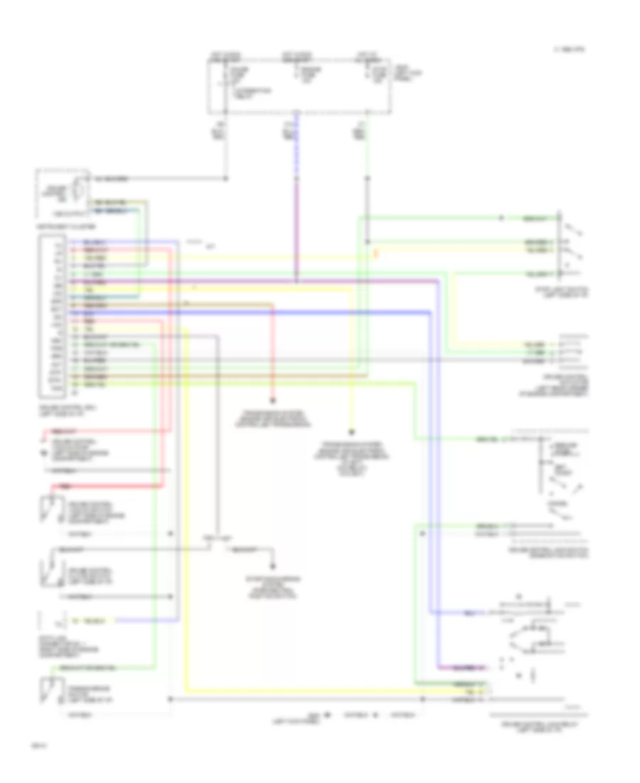
Cruise Control Wiring Diagram for Toyota Pickup SR5 1994
List of elements for Cruise Control Wiring Diagram for Toyota Pickup SR5 1994:
- 1995 vftc c
- A/t
- Act
- C13
- Cancel
- Ccs
- Cruise control actuator (left rear corner of engine compartment)
- Cruise control clutch switch (left side of i/p)
- Cruise control ecu (left side of i/p)
- Cruise control ind
- Cruise control main relay (left side of i/p)
- Cruise control main switch (combination switch)
- Cruise control vacuum pump (left side of engine compartment)
- Cruise control vacuum switch (left side of engine compartment)
- Data link connector no. 1 (right side of engine compartment)
- Ect
- Engine fuse 10a
- G200 (left kick panel)
- Gauge fuse 10a
- Hot at all times
- Hot in run and start
- Igb
- Igc
- Instrument cluster
- Integration relay
- J/b #1 (left kick panel)
- M/t
- N&c
- O/d
- Parking brake switch (left side of i/p)
- Pkb
- Red
- Resume/ accel
- Set/ coast
- Spd
- Starting/charging system (park/neutral position switch)
- Stop fuse 15a
- Stop light switch (left side of i/p)
- Stp+
- Stp-
- Transmission system (engine and electronic controlled transmission)
- Transmission system (engine and electronic controlled transmission) (w/ ect) (o/d relay) (w/o ect)
- Vac
- Vss output
 Русский