AUTOMOTIVE ELECTRICIANS PORTAL

CRUISE CONTROL – Toyota Venza XLE 2014 – SYSTEM WIRING DIAGRAMS

CRUISE CONTROL

2.7L

2.7L, Cruise Control Wiring Diagram for Toyota Venza XLE 2014

2.7L, Cruise Control Wiring Diagram for Toyota Venza XLE 2014 https://portal-diagnostov.com/license.html
https://portal-diagnostov.com/license.html Automotive Electricians Portal FZCO Automotive Electricians Portal FZCO
Download PDF file

List of elements for 2.7L, Cruise Control Wiring Diagram for Toyota Venza XLE 2014:
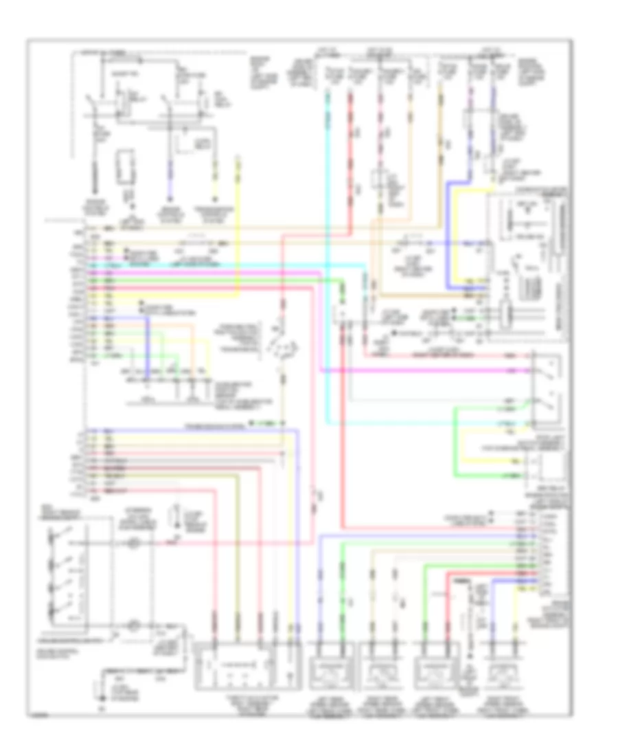
  • (left
  • (left front wheel hub assembly)
  • (left rear of engine) b5
  • (steering column) spiral cable sub-assembly
  • +bm
  • +res
  • -set
  • A4 (left front of engine compt)
  • A43
  • A49
  • A5 (left end of dash)
  • Accelerator position sensor (top of accelerator pedal assembly)
  • B5 (left rear of engine)
  • B58
  • Ba1
  • Ba2
  • Brake actuator assembly (right front of engine compt)
  • Brk relay
  • C/opn relay
  • C16
  • C24
  • C27
  • Can h
  • Can i/f
  • Can l
  • Cancel
  • Canh
  • Canl
  • Ccs
  • Combination meter assembly
  • Computer data lines system
  • Cruise control main switch
  • Cruise control switch
  • Cruise ind
  • D1 (right kick panel)
  • D18
  • D55
  • D57
  • Da2
  • Da5
  • De1
  • De2
  • Dome fuse 7.5a
  • Drive ic
  • Driver side j/b assembly (left end of dash)
  • E31
  • Ecm (left side of engine compt)
  • Ecu-b fuse 10a
  • Efi fuse 4 20a
  • Efi main 2 relay
  • Efi main fuse 20a
  • Efi main relay
  • Engine controls system
  • Engine room j/b (left side of engine compt)
  • Engine room r/b (left side of engine compt)
  • Epa
  • Epa2
  • Eta
  • Etcs fuse 10a
  • F12
  • F20
  • Fl+
  • Fl-
  • Fr+
  • Fr-
  • G25
  • G38
  • Gauge 1 fuse 10a
  • Gauge 2 fuse 7.5a
  • Ge01
  • Hot at all times
  • Hot in on or start
  • Ig2
  • Ign fuse 10a
  • Igsw
  • J/c a43 & d55 (left side of dash)
  • J/c a45 (left side of dash)
  • J/c a46
  • J/c d57 & e31 (right center of dash)
  • J/c d57 & e31 (right center of dash) e31
  • J/c d59 (center of dash)
  • J/c e32 (right end of dash)
  • La1
  • Lcd (a/t position)
  • Left front speed sensor
  • Left rear speed sensor (left rear wheel hub assembly)
  • Ma1
  • Micro processor
  • Mrel
  • Nca
  • Of dash)
  • On/off
  • Park/neutral position switch assembly (top of transmission)
  • Pnk
  • Power
  • Red
  • Right front speed sensor (right front wheel hub assembly)
  • Right rear speed sensor (right rear wheel hub assembly)
  • Rl+
  • Rl-
  • Rr+
  • Rr-
  • Set ind
  • Short pin
  • Side
  • Spd
  • St1-
  • Stop fuse 10a
  • Stop light switch assembly (top of brake pedal assembly)
  • Stp
  • Stp2
  • Tach
  • Throttle w/ motor body assembly (rear of engine)
  • Transmission control ecu assembly (left side of transmission)
  • Transmissions system
  • Vcp2
  • Vcpa
  • Vcta
  • Vpa
  • Vpa2
  • Vta1
  • Vta2

3.5L

3.5L, Cruise Control Wiring Diagram for Toyota Venza XLE 2014

3.5L, Cruise Control Wiring Diagram for Toyota Venza XLE 2014 https://portal-diagnostov.com/license.html
https://portal-diagnostov.com/license.html Automotive Electricians Portal FZCO Automotive Electricians Portal FZCO
Get access to all wiring diagrams of the carDownload PDF file

List of elements for 3.5L, Cruise Control Wiring Diagram for Toyota Venza XLE 2014:

  • (left side of dash)
  • (steering column) spiral cable sub-assembly
  • +bm
  • +res
  • -set
  • A/f fuse 20a
  • A/f relay
  • A4 (left front of engine compt)
  • A41
  • A43
  • A5 (left end of dash)
  • Accelerator position sensor (top of accelerator pedal assembly)
  • B39
  • Ba1
  • Ba2
  • Brake actuator assembly (right front of engine compt)
  • Brk relay
  • C/opn relay
  • C16
  • C24
  • C27
  • Can h
  • Can i/f
  • Can l
  • Cancel
  • Canh
  • Canl
  • Ccs
  • Combination meter assembly
  • Computer data lines system
  • Cruise control main switch
  • Cruise control switch
  • Cruise ind
  • D1 (right kick panel)
  • D18
  • D55
  • D57
  • Da2
  • Da5
  • De1
  • De2
  • Dome fuse 7.5a
  • Drive ic
  • Driver side j/b assembly (left end of dash)
  • E31
  • Ecm (right rear of engine compt)
  • Ecu-b fuse 10a
  • Efi main fuse 25a
  • Efi main relay
  • Engine controls system
  • Engine room j/b (left side of engine compt)
  • Engine room r/b (left side of engine compt)
  • Epa
  • Epa2
  • Eta
  • Etcs fuse 10a
  • F12
  • F18
  • F20
  • Fl+
  • Fl-
  • Fr+
  • Fr-
  • G25
  • G38
  • Gauge 1 fuse 10a
  • Gauge 2 fuse 7.5a
  • Ge01
  • Hot at all times
  • Hot in on or start
  • Ig2
  • Ign fuse 10a
  • Igsw
  • J/c a43 & d55 (left side of dash)
  • J/c a45 (left side of dash)
  • J/c a46
  • J/c b41 (top rear of engine)
  • J/c d57 & e31 (right center of dash)
  • J/c d59 (center of dash)
  • J/c e32 (right end of dash)
  • La1
  • Lcd a/t position
  • Left front speed sensor (left front wheel hub assembly)
  • Left rear speed sensor (left rear wheel hub assembly)
  • Ma1
  • Micro processor
  • Mrel
  • Nca
  • On/off
  • Park/neutral position switch assembly (top of transmission)
  • Pnk
  • Power
  • Red
  • Right front speed sensor (right front wheel hub assembly)
  • Right rear speed sensor (right rear wheel hub assembly)
  • Rl+
  • Rl-
  • Rr+
  • Rr-
  • Set ind
  • Short pin
  • Spd
  • St1-
  • Stop fuse 10a
  • Stop light switch assembly (top of brake pedal assembly)
  • Stp
  • Stp2
  • Tach
  • Throttle w/ motor body assembly (right rear of engine)
  • Transmissions controls system
  • Transmissions system
  • Vcp2
  • Vcpa
  • Vcta
  • Vpa
  • Vpa2
  • Vta1
  • Vta2