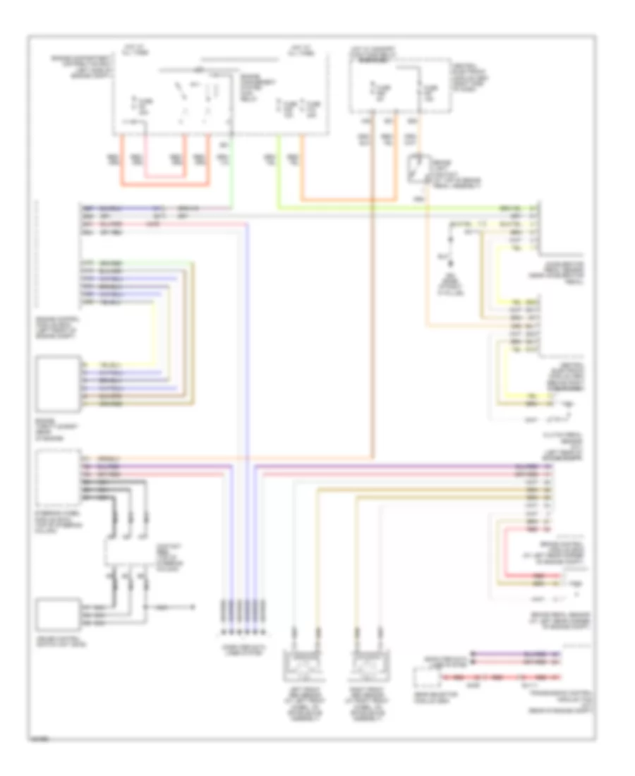
CRUISE CONTROL
Cruise Control Wiring Diagram for Volvo C70 T-5 2011
List of elements for Cruise Control Wiring Diagram for Volvo C70 T-5 2011:
- 64/111
- 64/90
- A14
- A19
- A45
- A65
- A74
- A75
- A88
- Accelerator pedal sensor (near accelerator pedal)
- B2 nca
- B26
- B27
- B3 nca
- B41
- B5 nca
- B54
- Brake control module (bcm) (at left rear corner of engine compt)
- Brake light contact (at top of brake pedal assembly)
- Brake pedal sensor (at left rear corner of engine compt)
- Central electronic module (cem) (behind right side of dash)
- Central electronic module (cem) (right side of dash)
- Clutch pedal sensor (m/t) (left rear of engine compt)
- Computer data lines system
- Contact reel (top of steering column)
- Cruise control switch unit (sws)
- E21
- E28
- E41
- Engine compartment distribution box (left side of engine compt)
- Engine control module (ecm) (left front of engine compt)
- Engine management system main relay
- Engine throttle body (rear of engine)
- Fuse f18 40a
- Fuse f36 10a
- Fuse f57 15a
- Fuse f68 5a
- Fuse f9 30a
- G12
- G21
- G22
- G23
- G31
- G84 (base of right "a" pillar)
- Gear selector module (gsm)
- Hot at all times
- Hot w/ comfort functions relay energized
- Left front abs sensor (at left front wheel, on spindle/hub assembly)
- Nca
- Red
- Right front abs sensor (at right front wheel, on spindle/hub assembly)
- Steering wheel module (swm) (top of steering column)
- Transmission control module (tcm) (a/t) (rear of engine compt)
 English