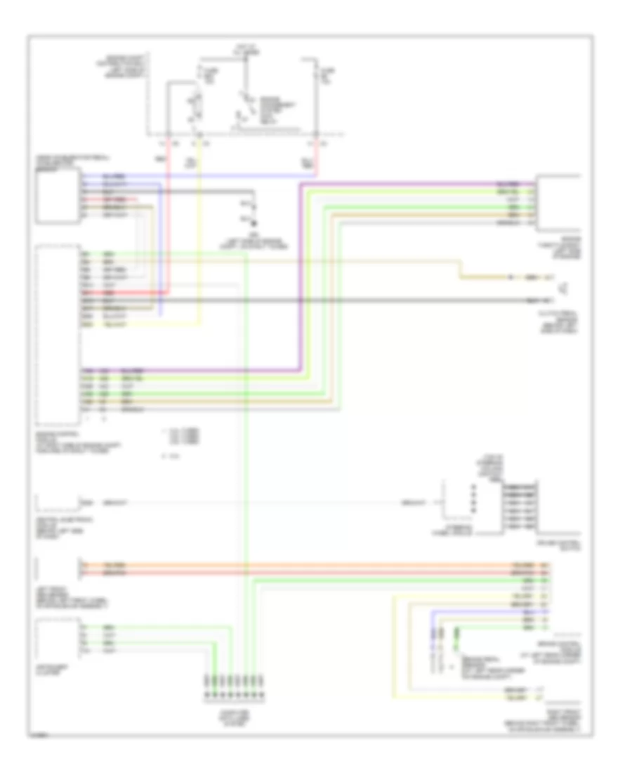
CRUISE CONTROL
Cruise Control Wiring Diagram for Volvo V70 2005
List of elements for Cruise Control Wiring Diagram for Volvo V70 2005:
- (near accelerator pedal) accelerator sensor
- (top of steering column) contact reel
- 2.4l
- 2.4l turbo,
- 2.5l turbo, 2.9l turbo
- A19
- A20
- A25
- A35
- A36
- A43
- A59
- B11
- B13
- B15
- B17
- B25
- B38
- Brake control module (at left rear corner of engine compt)
- Brake pedal sensor (at left rear corner of engine compt)
- Central electronic module (behind left side of dash)
- Clutch pedal sensor (behind left side of dash)
- Computer data lines system
- Cruise control switch
- D58
- Engine
- Engine compt distribution box (left side of engine compt)
- Engine control module (at right side of engine compt, forward of strut tower)
- Engine throttle body (left side of engine)
- Fuse b23 10a
- Fuse b8 10a
- G93 (left side of engine compt, on strut tower)
- Hot at all times
- Instrument cluster
- Left front abs sensor (behind left front wheel, on spindle/hub assembly)
- Management system main relay
- Nca
- Red
- Right front abs sensor (behind right front wheel, on spindle/hub assembly)
- Steering wheel module
 English