CRUISE CONTROL
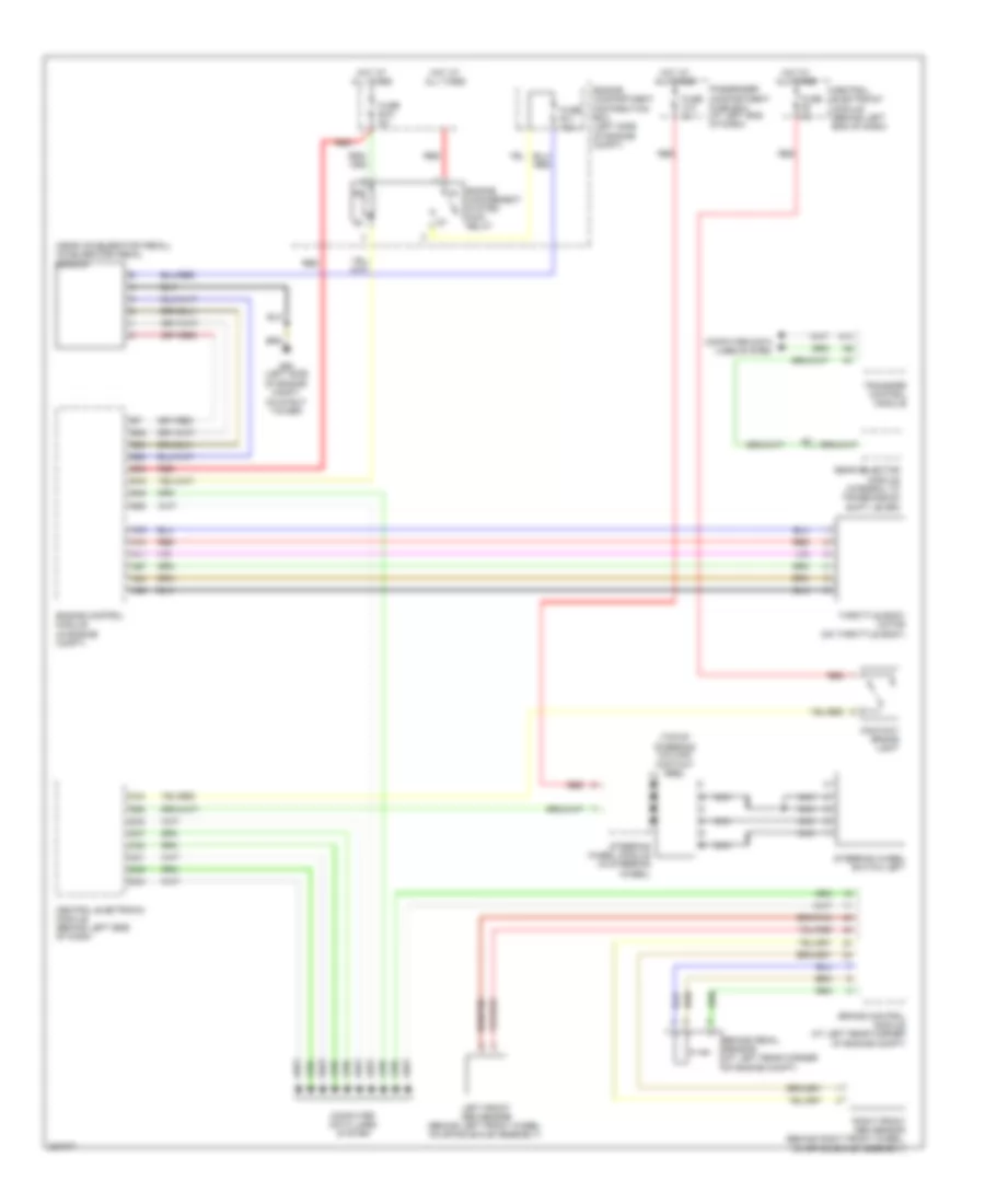
Cruise Control Wiring Diagram for Volvo XC90 R-Design 2009
List of elements for Cruise Control Wiring Diagram for Volvo XC90 R-Design 2009:
- (near accelerator pedal) accelerator pedal sensor
- (top of steering column) contact reel
- A11
- A14
- A24
- A65
- A67
- A74
- A75
- B16
- B24
- B28
- B32
- B45
- B54
- B58
- Brake control module (at left rear corner of engine compt)
- Brake pedal sensor (at left rear corner of engine compt)
- C21
- C22
- C34
- Central electronic module (behind left end of dash)
- Central electronic module (behind left side of dash)
- Computer data lines system
- Contact brake light
- D32
- D34
- D47
- D49
- D58
- Engine
- Engine compartment distribution box (left side of engine compt)
- Engine control module (in engine compt)
- Fuse b11 10a
- Fuse b19 5a
- Fuse c10 5a
- Fuse f9 5a
- G93 (left side of engine compt, on strut tower)
- Gear selector module (integral to transmission shift lever)
- Hot at all times
- Left front abs sensor (behind left front wheel, on spindle/hub assembly)
- Management system main relay
- Nca
- Passenger compartment fuse box (at left end of dash)
- Red
- Right front abs sensor (behind right front wheel, on spindle/hub assembly)
- Steering wheel module (in steering wheel)
- Steering wheel switch left
- Throttle body motor (on throttle body)
- Transfer control module
 English