COMPUTER DATA LINES
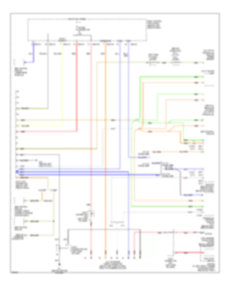
Computer Data Lines Wiring Diagram for Hyundai Tiburon GT 2005
List of elements for Computer Data Lines Wiring Diagram for Hyundai Tiburon GT 2005:
- (2.0l)
- (2.7l)
- (behind crash pad) (2.7l) j/c c141 (2.0l) j/c c41
- (left side of dash) j/c m34
- (on top of transaxle) vehicle speed sensor
- 12volt output
- 2.0l
- 2.0l w/ immobilizer
- 2.0l w/o immobilizer
- 2.7l
- 2.7l w/ immobilizer
- Abs control module (in right front corner of engine compartment)
- Bcm-ai
- Bcm-hm
- Bcm-im
- Bcm-jm
- Bcm-km
- Body control module box (behind left side of dash)
- C133-1
- C133-4
- C136-1
- C136-3
- C33-1
- C33-2
- Code save
- Data link connector (below left side of dash)
- Diag
- E/r box (in left front corner of engine compt, behind battery)
- Ecm/pcm (behind right side of dash, above kick panel)
- Esp air bleeding connector
- Esp control module
- Fuel pump relay
- Fuel sender & fuel pump motor (below center of rear seat)
- G11 (behind center of dash)
- G14 (behind left side of dash)
- Hot at all times
- Immo
- Joint connector m34 (left side of dash)
- Joint connector m35 (left side of dash)
- Joint connector m36 (left side of dash)
- Multi gauge unit
- Multipurpose check connector (below left side of dash, right of steering column)
- Nca motor
- Power connector 10a
- Red
- Srs control module (under rear console)
- Transaxle control module (2.7l) (behind left side of dash)
- Vertical resistor (w/o esp) (on top of transaxle)
- W/ esp
- W/o esp
 Dansk
Dansk Deutsch
 Ελληνικά
 English
 English
 Español
 Suomi
Suomi Français
 Français
 עברית
עברית Hrvatski
 Magyar
 Italiano
 日本語
日本語 한국어
한국어 Nederlands
 Polski
 Português
 Português
 Română
 Русский
 Slovenčina
 Slovenščina
 Svenska
 Türkçe
 中文 (中国)
 Čeština