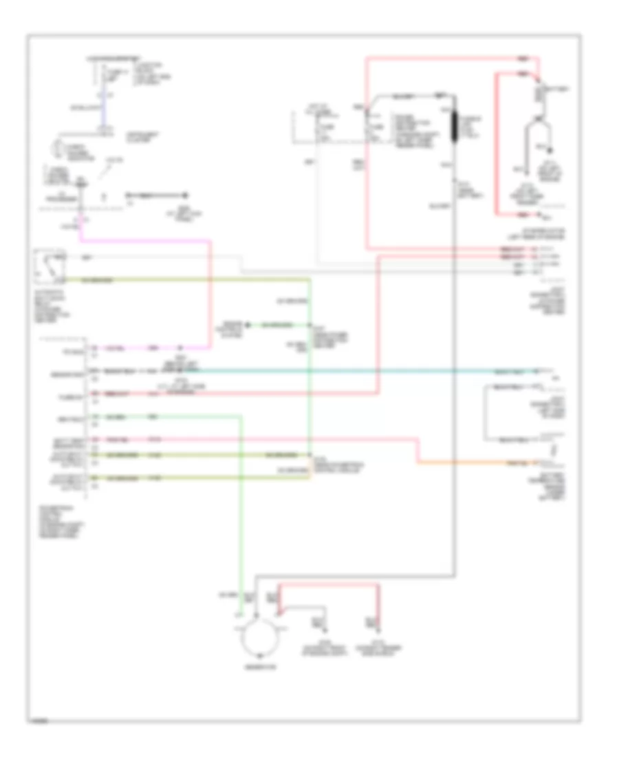
STARTING/CHARGING
Charging Wiring Diagram for Dodge Dakota 2004
List of elements for Charging Wiring Diagram for Dodge Dakota 2004:
- A14
- A142
- Auto shut- down relay out put
- Automatic shut down relay (in power distribution center)
- B(+)
- Batt temp sensor sig
- Battery
- Battery temperature sensor (under battery)
- Check gauges ind ctrl
- Check gauges indicator
- D25
- Engine controls system
- Fuse 14 10a
- Fuse 20a
- Fuse 30a
- Fused b+
- G100 (on right front of engine compt)
- G110 (on left front inner fender)
- G111 (on left front of engine)
- G115 (on right fender side shield)
- G208 (at left kick panel)
- Gen field
- Generator
- Hot at all times
- Hot in run or start
- I/o processer
- Instrument cluster
- Joint connector 2 (in power distribution center)
- Joint connector 3 (left side of dash)
- Junction block (on left end of dash)
- K118
- K20
- Nca
- Pci bus
- Power distribution center (in engine compt, on left inner fender panel)
- Powertrain control module (in engine compt, on right inner fender panel)
- Red
- S100
- S103 (4.7l: at left side of engine)
- S141 (near battery)
- S176 (near powertrain control module)
- S187 (near power distribution center)
- S201 (behind left side of dash)
- Sensor gnd
- Starter motor (left rear of engine)
- Volts
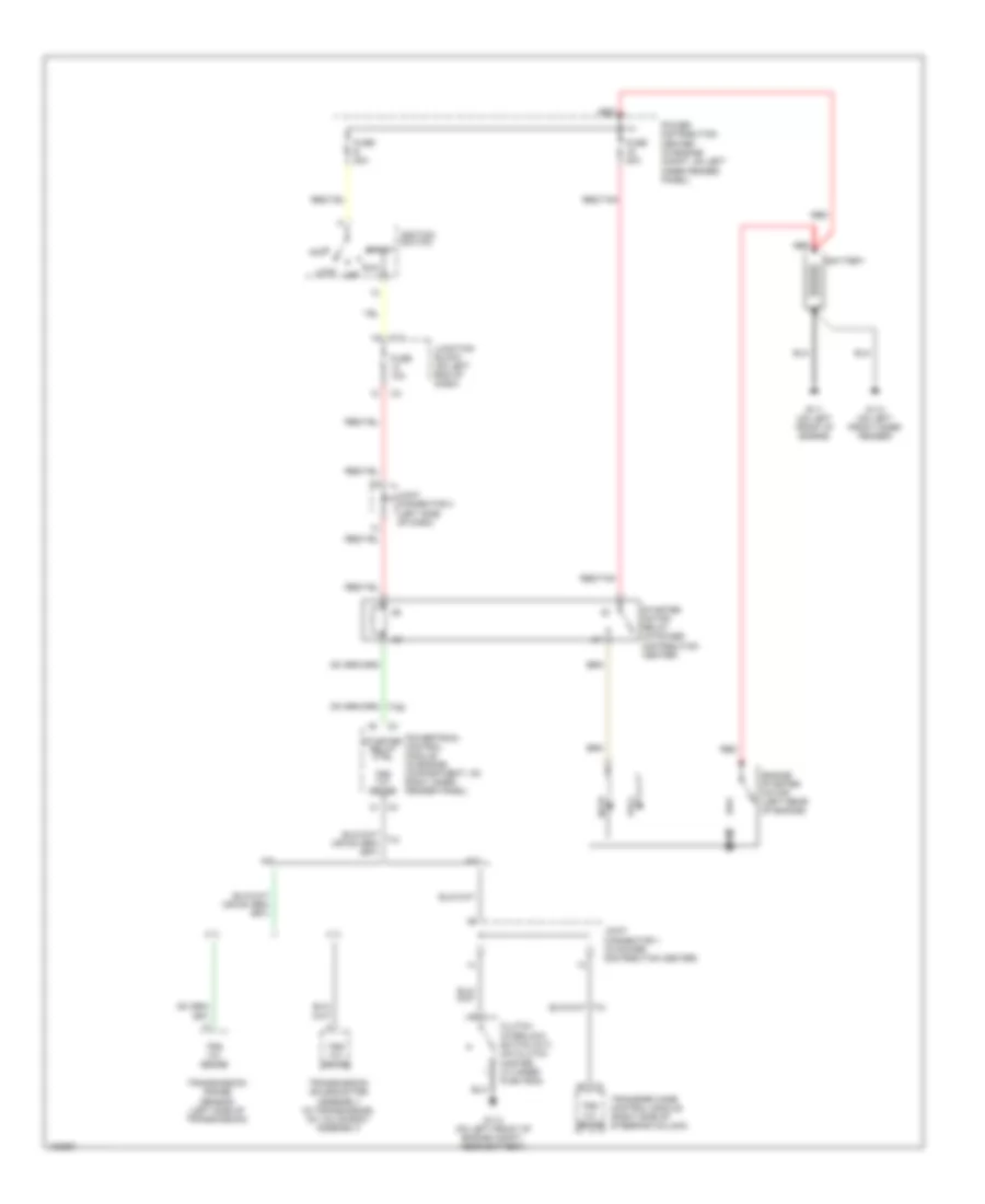
Starting Wiring Diagram for Dodge Dakota 2004
List of elements for Starting Wiring Diagram for Dodge Dakota 2004:
- (left side of dash)
- 3.7l
- 4.7l
- A/t
- Acc
- Battery
- C11
- Clutch interlock switch (m/t) (on clutch master cylinder push rod)
- Engine starter motor (left rear of engine)
- Fuse 10a
- Fuse 50a
- Fuse e 20a
- G110 (on left front inner fender)
- G111 (on left front of engine)
- G113 (on left front of engine compt, near battery)
- Hold- in
- Ignition switch
- Joint connector 1 (in power distribution center)
- Joint connector 3
- Junction block (on left end of dash)
- Lock
- M/t
- Off
- Power distribution center (in engine compt, on left inner fender panel)
- Powertrain control module (in engine compartment, on right inner fender panel)
- Pull- in
- Red
- Red/tan
- Run
- Start
- Starter motor relay (in power distribution center)
- Starter relay ctrl
- Transfer case control module (right side of steering column)
- Transmission range sensor (left side of transmission)
- Transmission solenoid/trs assembly (in transmission, on valve body assembly)
- Trs t41 sense
 Dansk
Dansk Deutsch
 Ελληνικά
 English
 English
 Español
 Suomi
Suomi Français
 Français
 עברית
עברית Hrvatski
 Magyar
 Italiano
 日本語
日本語 한국어
한국어 Nederlands
 Polski
 Português
 Português
 Română
 Русский
 Slovenčina
 Slovenščina
 Svenska
 Türkçe
 中文 (中国)

 Čeština