AIR CONDITIONING
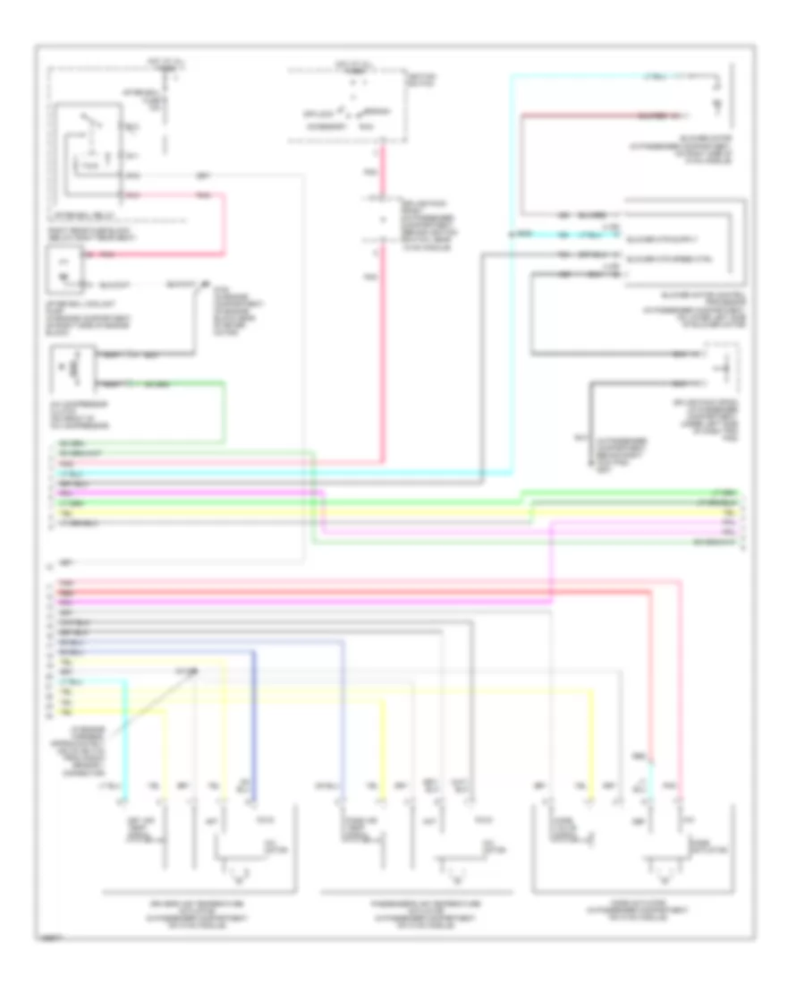
Automatic A/C Wiring Diagram (1 of 3) for Cadillac CTS 2003
 https://portal-diagnostov.com/license.html
Automotive Electricians Portal FZCO
Automotive Electricians Portal FZCO
https://portal-diagnostov.com/license.html
https://portal-diagnostov.com/license.html
Automotive Electricians Portal FZCO
Automotive Electricians Portal FZCO
List of elements for Automatic A/C Wiring Diagram (1 of 3) for Cadillac CTS 2003:
- 5 volt reference
- After boil pump relay ctrl
- Air inlet motor
- Amb air temp sensor sig
- Ambient light sensor signal
- Battery
- Blower fuse 40a
- Blower mtor speed ctrl
- Blower relay
- Blower relay ctrl
- Ccp fuse 10a
- Comp clutch fuse 10a
- Comp clutch relay
- Coolant level switch signal
- Door a
- Door b
- Dr air temp door ctrl b
- Driver air temp door ctrl a
- Driver air temp posit signal
- E10
- E11
- E12
- E13
- E14
- E15
- E16
- Evap low temp sens signal
- Evaporator temperature sensor
- F10
- F11
- F12
- F13
- F14
- F15
- F16
- G201 (in passenger compartment, behind right kick pad)
- Ground
- Hot at all times
- Hot in run
- Hvac control module (behind center of dash, below radio)
- Ign 3 fuse 10a
- Ignition 3 voltage
- Inside air temp sensor sig
- Inside air temperature sensor
- Left rear fuse block (below left rear seat)
- Left sunload sensor signal
- Low reference
- Mode door ctrl a
- Mode door ctrl b
- Mode door position signal
- Nca
- Pass air temp door ctrl a
- Pass air temp door ctrl b
- Pass air temp posit signal
- Pnk
- R51
- R52
- R53
- R54
- R55
- R56
- R57
- R58
- Recirc door ctrl a
- Recirc door ctrl b
- Recirculation actuator (on hvac module module, left of blower motor)
- Red
- Right sunload sensor signal
- S117
- Serial data
- Solid state
- Splice pack sp302 (in passenger compartment, on left frame rail, near left side of driver's seat)
- Sunload sensor (at front center of passenger compartment, on defroster grill)
- Underhood fuse block (at left front of engine compartment)
- Volt
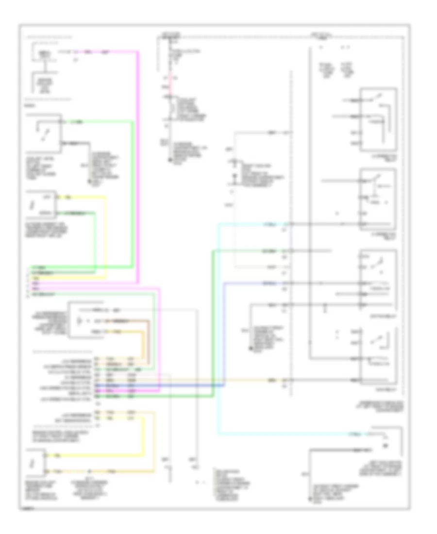
Automatic A/C Wiring Diagram (2 of 3) for Cadillac CTS 2003
List of elements for Automatic A/C Wiring Diagram (2 of 3) for Cadillac CTS 2003:
- (in engine harness, approximately 235 cm (98.3 in) from knock sensor 1 connector)
- (in passenger compartment, behind right kick pad) g201
- 2 (or 4)
- 4 (or 2)
- A/c
- A/c compressor clutch (on front of a/c compressor)
- Accessory
- After boil coolant pump (in engine compartment, on right side of engine block)
- After boil fuse 10a
- After boil relay
- Blower motor (in passenger compartment, on right side of hvac module)
- Blower motor control processor (in passenger compartment, on lower left side of blower motor)
- Blower mtr speed ctrl
- Cold
- Crank
- Def
- Driver's air temperature actuator (in passenger compartment, on hvac module)
- Dry air temp signal
- G100 (in engine compartment, on engine block near starter motor)
- Hot
- Hot at all times
- Ignition switch
- Mix motor
- Mode actuator
- Mode actuator (in passenger compartment, on hvac module)
- Mode valve signal
- Nca
- Off/lock
- Pass air temp signal
- Passenger's air temperature actuator (in passenger compartment, on hvac module)
- Pnk
- R11
- R12
- R13
- R15
- Red
- Right rear fuse block (below right rear seat)
- Run
- S118
- S323
- Splice pack sp201 (in passenger compartment, behind ignition switch, near hvac module)
- Splice pack sp203 (in passenger compartment, under left side of dash trim pad)
Automatic A/C Wiring Diagram (3 of 3) for Cadillac CTS 2003
List of elements for Automatic A/C Wiring Diagram (3 of 3) for Cadillac CTS 2003:
- (in engine compartment, near left front strut tower at bottom of inside fender well) g101
- (in engine compartment, on engine block near starter motor) g100
- (on right front corner of vehicle, on right body rail near right headlamp) g104
- 5v reference
- 87a
- A/c clutch relay ctrl
- A/c refrig press sensor
- A/c refrigerant pressure sensor (in engine compartment, near left front stut tower)
- Coolant bypass solenoid (at upper right corner of radiator)
- Coolant level switch (in left front corner of coolant surge tank)
- Ect sensor signal
- Engine control module (ecm) (at right front corner of engine compartment)
- Engine coolant low level
- Engine coolant temperature sensor (on top rear of intake manifold)
- Feed
- Hi speed fan relay
- High (or hi) fuse 30a
- High speed fan relay ctrl
- Hot at all times
- Hot in on or start
- Htr/vlv/cltch fuse 10a
- Left cooling fan (at front of engine compartment, in left side of fan assembly)
- Lo speed fan relay
- Low
- Low fan fuse 30a
- Low reference
- Low speed fan relay ctrl
- Main relay
- Main relay ctrl
- Outside ambient air temperature sensor (under front bumper, near front grille)
- Pnk
- R39
- R40
- R41
- R42
- R47
- R48
- R49
- R50
- Radio
- Right cooling fan (at front of engine compartment, in right side of fan assembly)
- Rtn
- S/p fan relay
- S111 (in engine harness, approximately 120 cm (31.5 in) from ho2s bank 2 sensor 1)
- Serial data
- Sig
- Signal
- Splice pack sp102 (in right front corner of engine compartment, in front of underhood fuse block
- Tan
- Underhood fuse block (at left front of engine compartment)
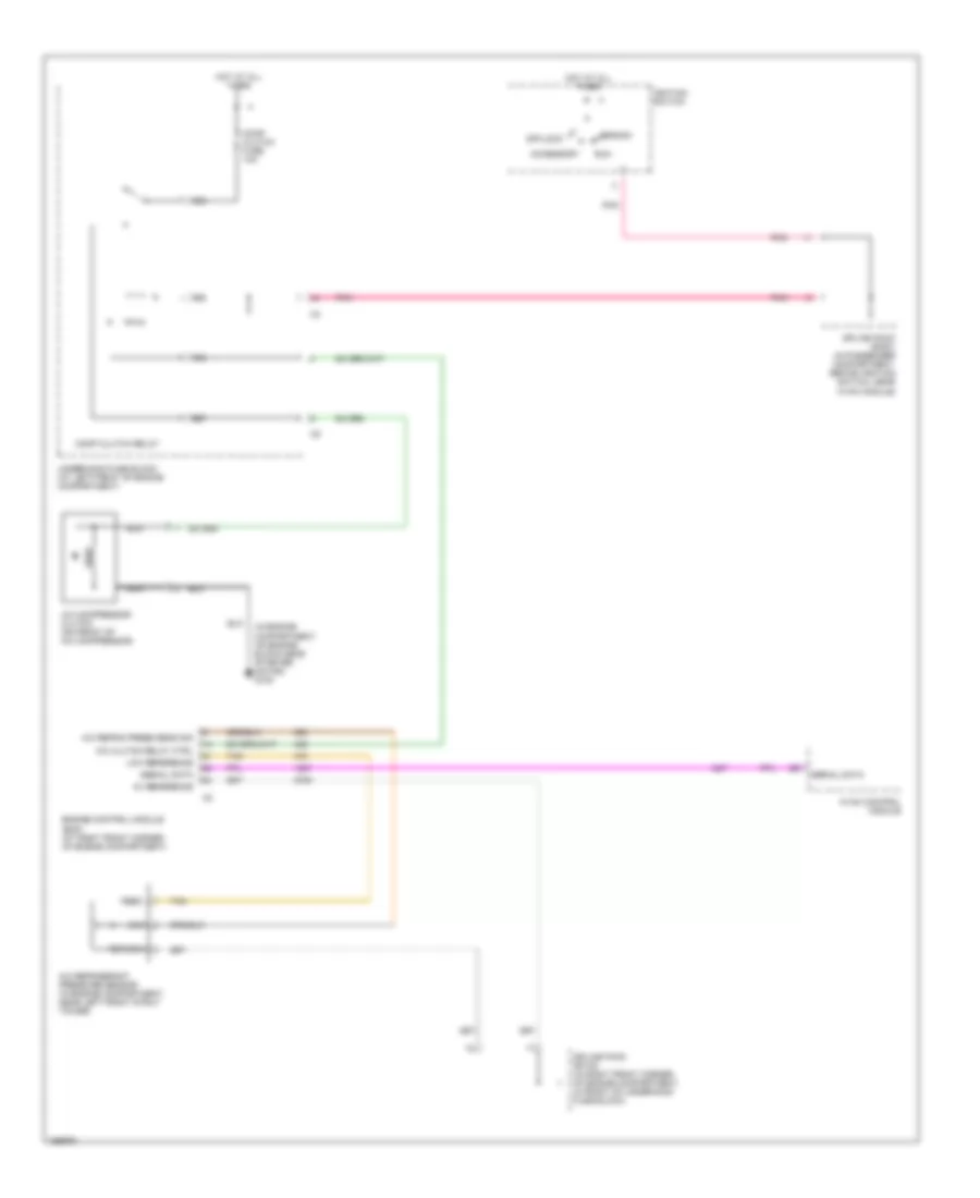
Compressor Wiring Diagram for Cadillac CTS 2003
List of elements for Compressor Wiring Diagram for Cadillac CTS 2003:
- (in engine compartment, on engine block near starter motor) g100
- 5v reference
- A/c clutch relay ctrl
- A/c compressor clutch (on front of a/c compressor)
- A/c refrig press sens sig
- A/c refrigerant pressure sensor (in engine compartment, near left front strut tower)
- Accessory
- Comp clutch fuse 10a
- Comp clutch relay
- Crank
- Engine control module (ecm) (at right front corner of engine compartment)
- Feed
- Hot at all times
- Hvac control module
- Ignition switch
- Low reference
- Nca
- Off/lock
- Pnk
- R55
- R56
- R57
- R58
- Return
- Run
- Serial data
- Sig
- Splice pack sp102 (in right front corner of engine compartment, in front of underhood fuse block)
- Splice pack sp201 (in passenger compartment, behind ignition switch, near hvac module)
- Tan
- Underhood fuse block (at left front of engine compartment)

 Dansk
Dansk Deutsch
 Ελληνικά
 English
 English
 Español
 Suomi
Suomi Français
 Français
 עברית
עברית Hrvatski
 Magyar
 Italiano
 日本語
日本語 한국어
한국어 Nederlands
 Polski
 Português
 Português
 Română
 Русский
 Slovenčina
 Slovenščina
 Svenska
 Türkçe
 中文 (中国)