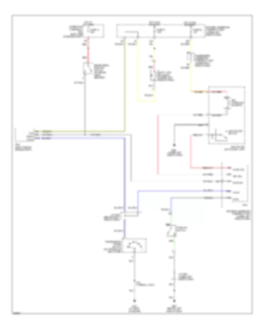
SHIFT INTERLOCK
Shift Interlock Wiring Diagram for Honda Odyssey EX 2007
List of elements for Shift Interlock Wiring Diagram for Honda Odyssey EX 2007:
- (under left side of dash)
- A16
- Atp-p
- Bksw
- Brake pedal position switch (on brake pedal bracket)
- Driver's underdash fuse/relay box
- Driver's underdash fuse/relay box (under left side of dash)
- Fuse 13 20a
- Fuse 21 7.5a
- Fuse 32 10a
- G101 (at rear of engine)
- G501 (behind left side of dash)
- G502
- Hot at all times
- Hot in acc or start
- Hot in on or start
- Ig key sw
- Ignition key switch
- Ignition key switch/key light
- J/c c405 (behind right side of dash)
- J/c c502 (under left side of dash)
- Key interlock solenoid
- Key sol
- Micu
- N26
- N36
- P-pin
- P13
- P29
- P30
- Park pin switch
- Passenger's underdash fuse/relay box (under right side of dash)
- Pcm (right side of engine compt)
- Red
- S10 (thermal joint)
- Shift lock solenoid (under left side of dash)
- Sls
- Stop sw
- Transmission range switch (on transaxle end cover)
- Under-hood fuse/relay box (right side of engine compt)
- X34
 Dansk
Dansk Deutsch
 Ελληνικά
 English
 English
 Español
 Suomi
Suomi Français
 Français
 עברית
עברית Hrvatski
 Magyar
 Italiano
 日本語
日本語 한국어
한국어 Nederlands
 Polski
 Português
 Português
 Română
 Русский
 Slovenčina
 Slovenščina
 Svenska
 Türkçe
 中文 (中国)
 Čeština