SHIFT INTERLOCK
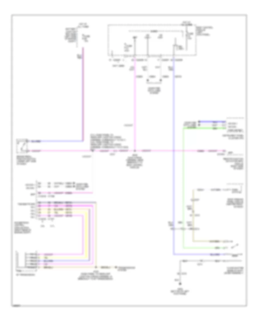
Shift Interlock Wiring Diagram for Lincoln MKS 2013
List of elements for Shift Interlock Wiring Diagram for Lincoln MKS 2013:
- (3.7l: dash panel to headlamp junction wiring harness, in breakout to c211) (3.5l: dash panel to headlamp junction wiring harness, in breakout to c1100a) s111
- (not used)
- 3.5l
- 3.7l
- 6f transmission
- Battery junction box (bjb) (left side of engine compt)
- Body control module (left kick panel)
- Bpp
- Brake pedal position switch (under left side of dash)
- Bsi (fet)
- C1381b
- C1381e
- C175b
- C175t
- C210
- C212
- C214
- C215
- C2153c
- C2280b
- C2280f
- C237
- Ccb08
- Cdc41
- Cet53
- Computer data lines system
- Floor shifter (base of shift lever assembly)
- Fuse 10a
- Fuse 5a
- G302 (bottom of left kick panel)
- Hot at all times
- Hs can +
- Hs can -
- Instrument panel cluster (ipc)
- Micro
- Park detect
- Park status
- Powertrain control module (pcm) (right rear of engine compt)
- Remote function actuator (rfa) module (right side of dash)
- Ret24
- Roof opening panel module (center front of roof)
- S100 (dash panel to headlamp junction wiring harness, in breakout to 6f transmission)
- S245 (main wiring harness, near breakout to body control module)
- Tr 1
- Tr 2
- Tr 3
- Tr 4
- Tr gnd
- Transmissions system
- Trs
- Tss/oss/tr gnd
- Vdb04
- Vdb05
- Vet29
- Vet30
- Vet31
- Vet32
 Dansk
Dansk Deutsch
 Ελληνικά
 English
 English
 Español
 Suomi
Suomi Français
 Français
 עברית
עברית Hrvatski
 Magyar
 Italiano
 日本語
日本語 한국어
한국어 Nederlands
 Polski
 Português
 Português
 Română
 Русский
 Slovenčina
 Slovenščina
 Svenska
 Türkçe
 中文 (中国)
 Čeština