COMPUTER DATA LINES
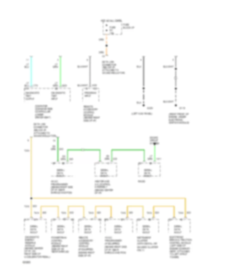
Data Link Connector Wiring Diagram for Oldsmobile Ninety-Eight Regency 1994
List of elements for Data Link Connector Wiring Diagram for Oldsmobile Ninety-Eight Regency 1994:
- (left kick panel)
- (right front of engine, under electronic ignition module)
- A11
- B11
- Computer command ride controller (under driver seat)
- Data link connector (below i/p, attached to sound insulator)
- Diagnostic energy reserve module (behind center of i/p, on right side of accelerator pedal)
- Diagnostic test input
- Diagnostic test output
- E10
- E11
- Electronic brake & traction control module (left side of engine compart- ment, attached to left strut tower)
- Fuse 9c 10a
- Fuse block:i/p
- G119
- G200
- Heater and a/c control assembly (behind center of i/p)
- Hot at all times
- Hvac programmer (behind right side of i/p, near shroud and pcm)
- Hvac programmer (if equipped) (behind right side of i/p, near shroud and pcm)
- Instrument cluster (with digital or gauges cluster only)
- Powertrain control module (behind right side of i/p) near shroud)
- Program input
- Radio
- Remote accessory control module (behind right side of i/p)
- Remote accessory control module (if equipped) (behind right side of i/p)
- Serial data in/out
- Sound circuit system
- Tan
 Dansk
Dansk Deutsch
 Ελληνικά
 English
 English
 Español
 Suomi
Suomi Français
 Français
 עברית
עברית Hrvatski
 Magyar
 Italiano
 日本語
日本語 한국어
한국어 Nederlands
 Polski
 Português
 Português
 Română
 Русский
 Slovenčina
 Slovenščina
 Svenska
 Türkçe
 中文 (中国)
 Čeština