ENGINE PERFORMANCE
4.4L TWIN TURBO
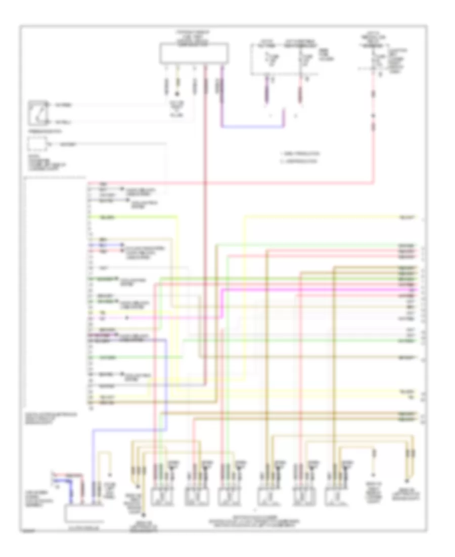
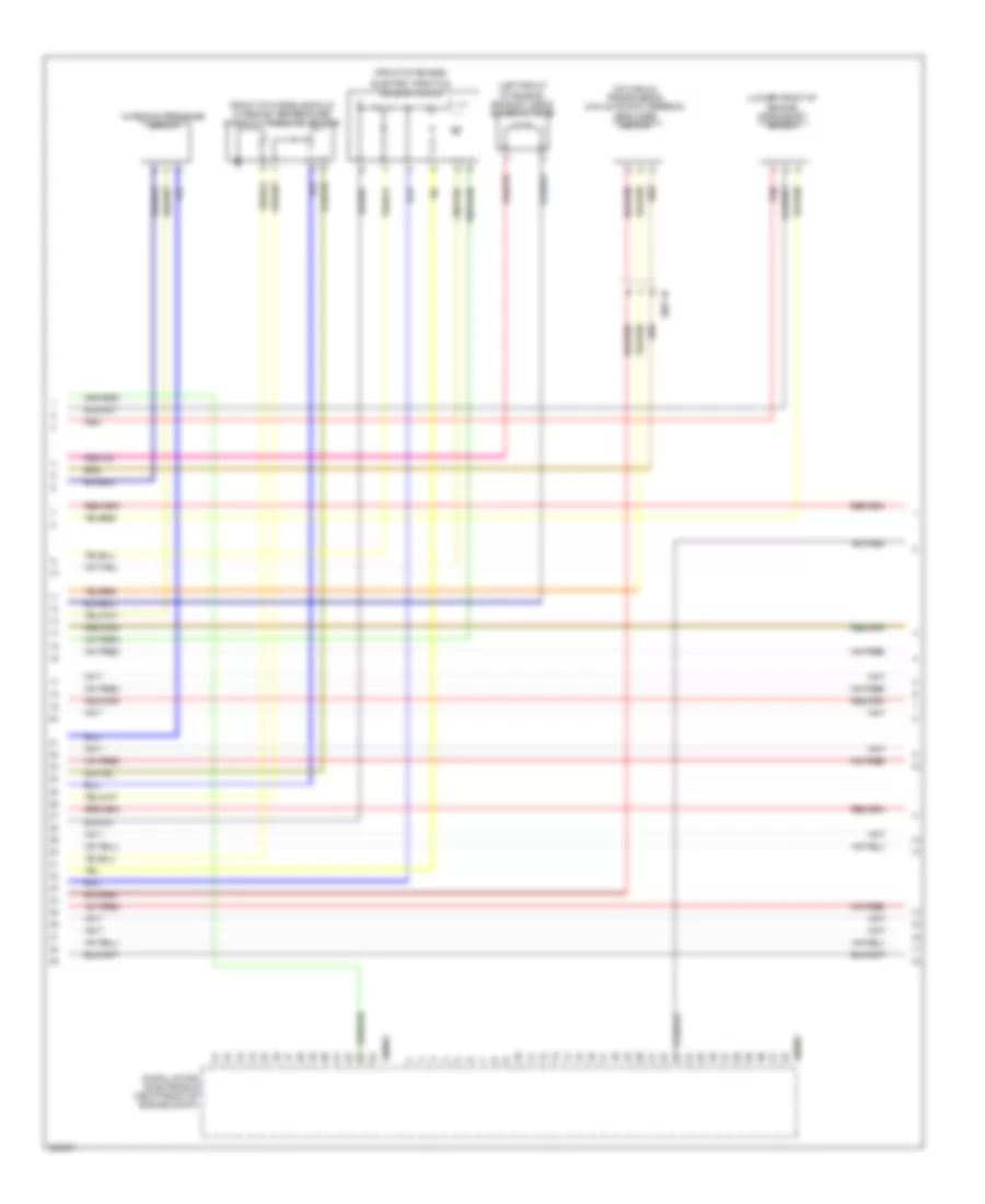
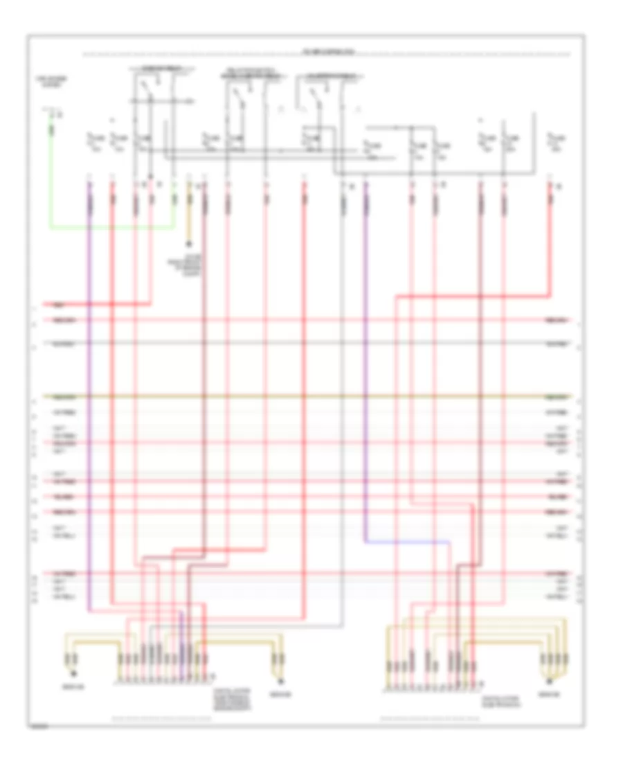
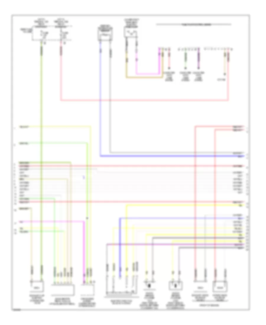
4.4L Twin Turbo, Engine Performance Wiring Diagram, A/T (1 of 11) for BMW 650i 2012
List of elements for 4.4L Twin Turbo, Engine Performance Wiring Diagram, A/T (1 of 11) for BMW 650i 2012:
- (right rear of luggage compt)
- (top right side of fuel tank) natural vacuum leak detection
- 11b
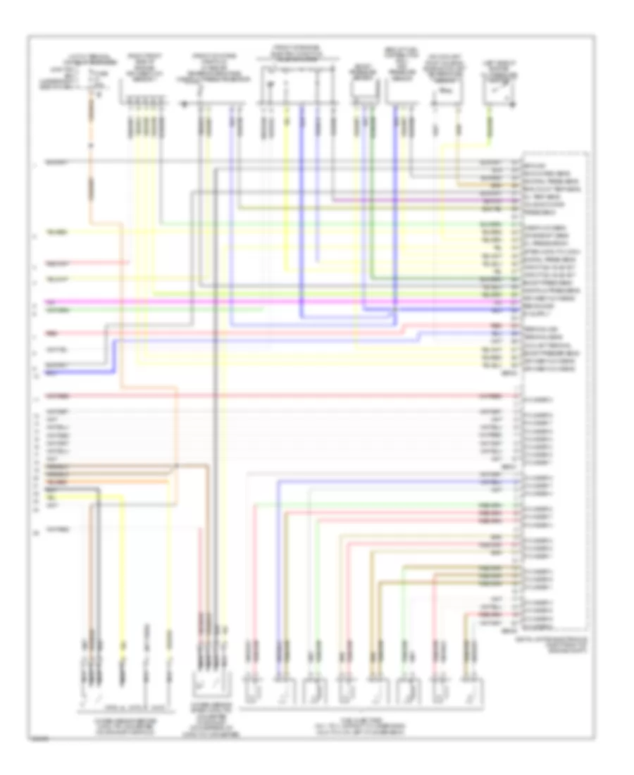
- Car access system (w/o automatic gearbox)
- Clutch module
- Computer data lines system
- Cooling fans system
- Dc/dc converter (under left side of luggage compt)
- Digital motor electronics (right front of engine compt)
- Early production
- Fuse 10a
- Fuse 5a
- Hot at all times
- Hot w/ bistable relay energized
- Hot w/ terminal 30b relay energized
- Ignition coils cylinder (ignition coils 1, 2, 3 & 4: on right cylinder bank) (ignition coils 5 & 6: on left cylinder bank)
- Junction box (under right side of dash)
- Late production
- Nca
- Pressure switch
- Rear fuse holder
- Red
- Spark plug
- Z10 13b (right "c" pillar)
- Z10 9b (left kick panel)
- Z6000 1b
- Z6000 2b (left front of engine compt)
- Z6000 3b right front of engine compt
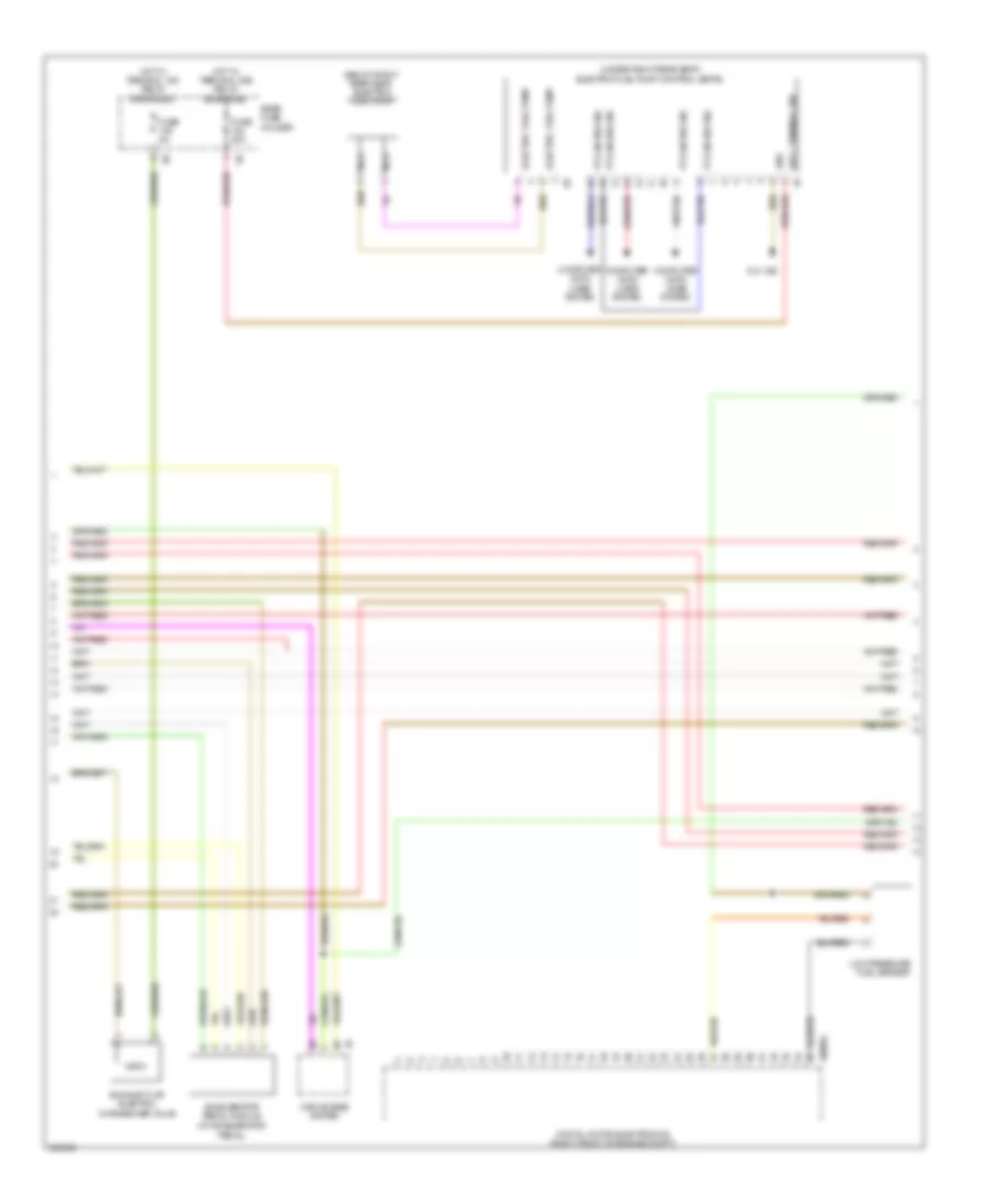
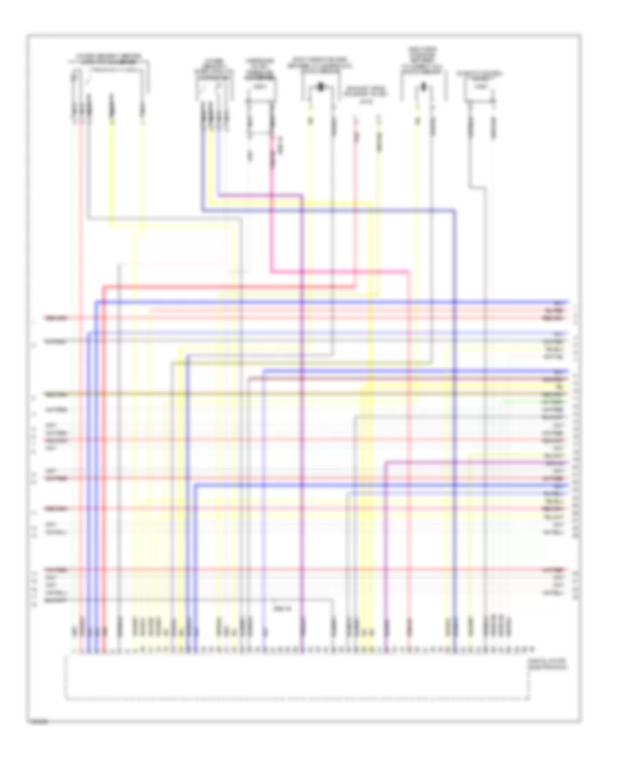
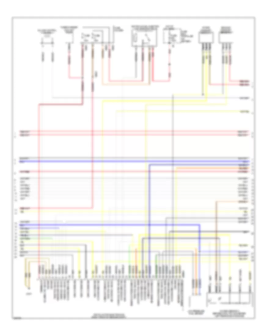
4.4L Twin Turbo, Engine Performance Wiring Diagram, A/T (2 of 11) for BMW 650i 2012
List of elements for 4.4L Twin Turbo, Engine Performance Wiring Diagram, A/T (2 of 11) for BMW 650i 2012:
- (at accelerator pedal)
- (below right rear seat) electric fuel pump
- (under right rear seat) electric fuel pump control (ekps)
- Accelerator pedal module
- Car access system
- Computer data lines system
- Digital motor electronics (right front of engine compt)
- Electric fuel pump
- Exhaust flap electric changeover valve
- Fuse 20a
- Fuse 5a
- Gnd
- Hot w/ terminal 15n relay energized
- Hot w/ terminal 30b relay energized
- Low pressure fuel sensor
- Nca
- Pt-can bus sig
- Rear fuse holder
- Sply, terminal 30b
- X60004
- Z10 18b
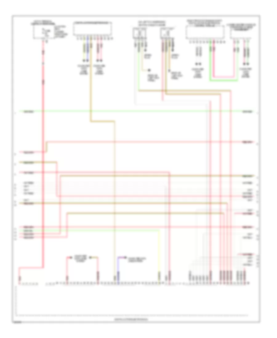
4.4L Twin Turbo, Engine Performance Wiring Diagram, A/T (3 of 11) for BMW 650i 2012
List of elements for 4.4L Twin Turbo, Engine Performance Wiring Diagram, A/T (3 of 11) for BMW 650i 2012:
- (on left cylinder bank)
- (right front of engine compt) digital motor electronics control module
- (under center console) integrated chassis management
- Computer data lines system
- Digital motor electronics 2
- Fuse 10a
- Hot w/ terminal 30b relay energized
- Ignition coils cylinder
- Junction box (under right side of dash)
- Nca
- Pnk
- Red
- Spark plug
- Z6000 4b (left kick panel)
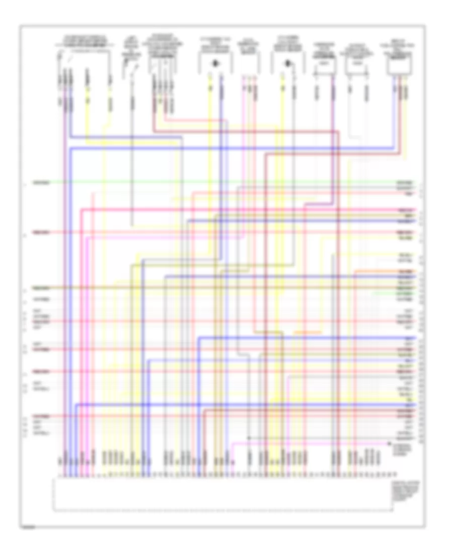
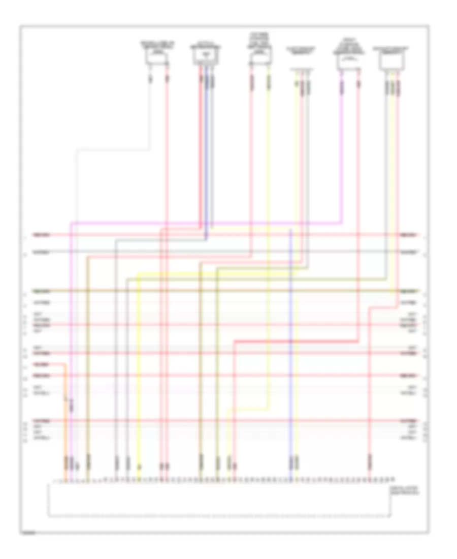
4.4L Twin Turbo, Engine Performance Wiring Diagram, A/T (4 of 11) for BMW 650i 2012
List of elements for 4.4L Twin Turbo, Engine Performance Wiring Diagram, A/T (4 of 11) for BMW 650i 2012:
- (cylinders 1 & 2: right side of engine) knock sensor
- (cylinders 3 & 4: right side of engine) knock sensor
- (end of fuel-distribution rail) rail pressure sensor
- (in exhaust, downstream of catalytic converter) oxygen sensor after catalytic converter
- (in oil reservoir) oil level sensor
- (in right plenum box) quantity control valve
- (left side of engine) oil pressure switch
- (on exhaust manifold) oxygen sensor before catalytic converter
- Digital motor electronics (right front of engine compt)
- Nca
- Red
- Starting/ charging system
- Wastegate valve pressure converter
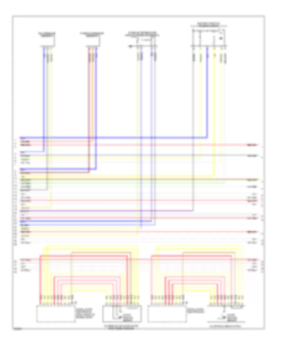
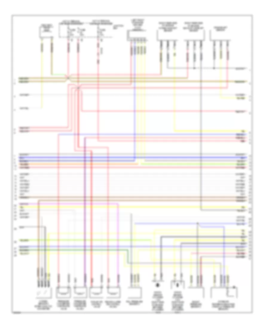
4.4L Twin Turbo, Engine Performance Wiring Diagram, A/T (5 of 11) for BMW 650i 2012
List of elements for 4.4L Twin Turbo, Engine Performance Wiring Diagram, A/T (5 of 11) for BMW 650i 2012:
- (front of engine)
- (left front of engine) exhaust vanos solenoid valve
- (lower front of engine) crankshaft sensor
- (on manual transmission) (w/o automatic gearbox) zero gear sensor
- Charging pressure sensor
- Digital motor electronics (right front of engine compt)
- Electric throttle valve actuator
- Front of intake manifold intake air temperature/ manifold pressure sensor
- Red
- X60002
- X60004
- X697 1b
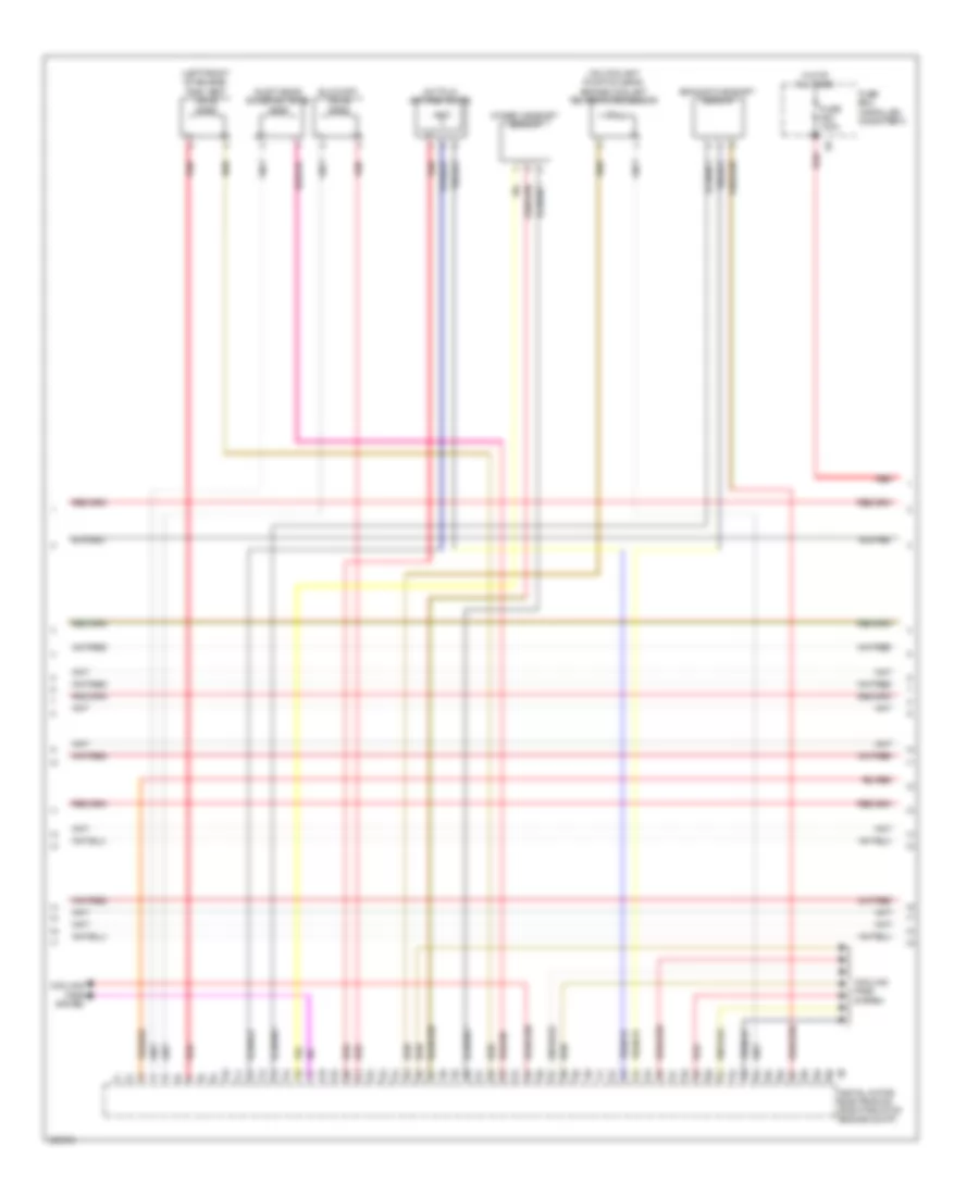
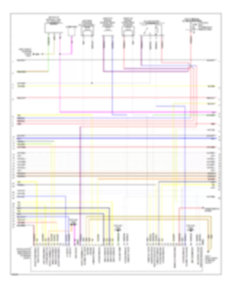
4.4L Twin Turbo, Engine Performance Wiring Diagram, A/T (6 of 11) for BMW 650i 2012
List of elements for 4.4L Twin Turbo, Engine Performance Wiring Diagram, A/T (6 of 11) for BMW 650i 2012:
- (right side of engine, between cylinders 5 & 6) knock sensor
- (right side of engine, between cylinders 7 & 8) knock sensor
- Digital motor electronics 2
- Exhaust vanos solenoid valve 2
- Nca
- Oxygen sensor 2 after catalytic converter
- Oxygen sensor 2 before catalytic converter
- Quantity control valve 2
- Red
- Wastegate valve 2 pressure converter
- X698 1b
4.4L Twin Turbo, Engine Performance Wiring Diagram, A/T (7 of 11) for BMW 650i 2012
List of elements for 4.4L Twin Turbo, Engine Performance Wiring Diagram, A/T (7 of 11) for BMW 650i 2012:
- Charging pressure sensor 2
- Digital motor electronics (right front of engine compt)
- Digital motor electronics 2
- Electric throttle valve actuator 2
- Intake air temperature/ manifold pressure sensor 2
- Motor position sensor
- Rail pressure sensor 2
- Red
- Valvetronic actuator motor (right side of engine)
- Valvetronic servomotor 2
4.4L Twin Turbo, Engine Performance Wiring Diagram, A/T (8 of 11) for BMW 650i 2012
List of elements for 4.4L Twin Turbo, Engine Performance Wiring Diagram, A/T (8 of 11) for BMW 650i 2012:
- (left front of engine) tank vent valve
- (on coolant pump housing) engine coolant temperature sensor
- Blow-off valve
- Cooling fans system
- Digital motor electronics (right front of engine compt)
- Exhaust camshaft sensor
- Fuse 100a
- Fuse box (installed on battery)
- Hot at all times
- Hot film air mass meter
- Inlet vanos solenoid valve
- Intake camshaft sensor
- Red
4.4L Twin Turbo, Engine Performance Wiring Diagram, A/T (9 of 11) for BMW 650i 2012
List of elements for 4.4L Twin Turbo, Engine Performance Wiring Diagram, A/T (9 of 11) for BMW 650i 2012:
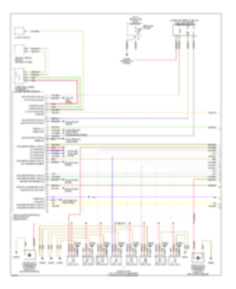
- Car access system
- Digital motor electronics (right side of engine compt)
- Digital motor electronics 2
- Dme main relay
- Fuse 10a
- Fuse 15a
- Fuse 20a
- Fuse 40a
- Power distribution
- Red
- Relay for ignition & fuel injection relay
- Valvetronic relay
- Z10 3b (right front of engine compt)
- Z6000 5b
- Z6000 6b
4.4L Twin Turbo, Engine Performance Wiring Diagram, A/T (10 of 11) for BMW 650i 2012
List of elements for 4.4L Twin Turbo, Engine Performance Wiring Diagram, A/T (10 of 11) for BMW 650i 2012:
- (front of engine) intake vanos solenoid valve 2
- (top rear of engine) fuel tank vent valve 2
- Digital motor electronics 2
- Exhaust camshaft sensor 2
- Hot film air mass meter 2
- Inlet camshaft sensor 2
- Recirculated air control valve 2
- Red
- X698 1b
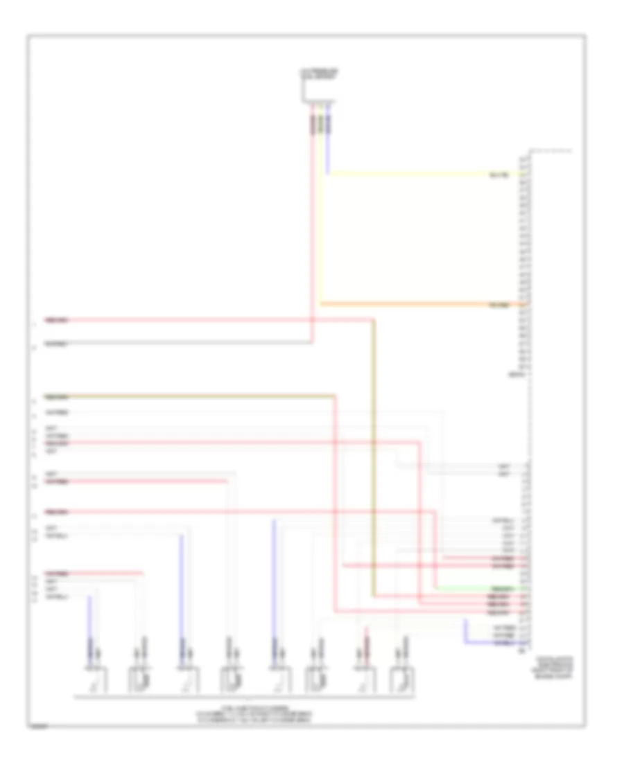
4.4L Twin Turbo, Engine Performance Wiring Diagram, A/T (11 of 11) for BMW 650i 2012
List of elements for 4.4L Twin Turbo, Engine Performance Wiring Diagram, A/T (11 of 11) for BMW 650i 2012:
- Digital motor electronics (right front of engine compt)
- Fuel injection cylinders (cylinders 1, 2, 3 & 4: on right cylinder bank) (cylinders 5, 6, 7 & 8: on left cylinder bank)
- Low pressure fuel sensor
- X60002
4.4L Twin Turbo, Engine Performance Wiring Diagram, M/T (1 of 6) for BMW 650i 2012
List of elements for 4.4L Twin Turbo, Engine Performance Wiring Diagram, M/T (1 of 6) for BMW 650i 2012:
- (under left rear of vehicle) fuel tank leakage diagnostic module
- Accelerator pedal module
- Activation solenoid
- Cas bus sig
- Central gateway module (left end of dash)
- Clutch module
- Clutch module sig
- Computer data lines system
- Cooling fans system
- Digital motor electronics (right front of engine compt)
- Electric changeover valve
- Electric fan activation
- Flexray bus sig
- Fuse 5a
- Gnd temperature sens
- Hot w/ terminal 30b relay energized
- Ignition coils (1 to 4: on right cylinder bank) (5 to 8: on left cylinder bank)
- Ignition coils interference suppression capacitor (right side of engine)
- Ignition coils interference suppression capacitor 2 (left side of engine)
- Integrated chassis management (under center console)
- Lin bus sig
- Nca
- Pnk
- Power distribution system
- Pt-can bus sig
- Rear fuse holder
- Red
- Sig diagnostic module
- Spark plug
- Speed sig
- Start sig
- Temperature sensor sig
- Terminal 15
- Transmissions system
- Wake-up sig
- X64561
- X64562
- X64563
- X64564
4.4L Twin Turbo, Engine Performance Wiring Diagram, M/T (2 of 6) for BMW 650i 2012
List of elements for 4.4L Twin Turbo, Engine Performance Wiring Diagram, M/T (2 of 6) for BMW 650i 2012:
- (front of engine)
- (under right rear seat) electric fuel pump
- Accelerator pedal module (at accelerator pedal)
- Car access system (under center of rear shelf)
- Computer data lines system
- Electric throttle valve actuator 2
- Exhaust flap electric changeover valve
- Exhaust vanos solenoid valve 2
- Fuel pump control (ekps)
- Fuse 20a
- Fuse 5a
- Gear box temperature sensor
- Hot w/ terminal 15n relay energized
- Hot w/ terminal 30b relay energized
- Intake vanos solenoid valve 2
- Knock sensor cylinder 5 & 6 (right side of engine, between cylinders 5 & 6)
- Knock sensor cylinder 7 & 8 (right side of engine, between cylinders 7 & 8)
- Nca
- Rear fuse holder
- Red
- Z10 18b
4.4L Twin Turbo, Engine Performance Wiring Diagram, M/T (3 of 6) for BMW 650i 2012
List of elements for 4.4L Twin Turbo, Engine Performance Wiring Diagram, M/T (3 of 6) for BMW 650i 2012:
- (not used)
- Air control valve 2
- Air mass flow sens 2
- Camshaft sens 2
- Camshaft sensor 2
- Charcoal filter valve
- Digital motor electronics (right front of engine compt)
- Exhaust camshaft sensor 2
- Fuse 100a
- Fuse 30a
- Fuse box (installed on battery)
- Fuse holder
- Gnd rail press sens 2
- Ground
- Hot at all times
- Ign coils & fuel inj
- Ignition & fuel injection load shedding relay
- Intake camshaft sensor 2
- Knock sens sig
- Low press fuel sens
- Low pressure fuel sensor
- Manifold press sens 2
- Nca
- Oxygen sens 2 gnd
- Oxygen sens 2 sig
- Oxygen sensor 2 before catalytic converter (left rear side of engine)
- Red
- Terminal 87
- Throttle valve 2
- Turbocharger coolant pump
- Vanes sol valve 2
- Volume control valve 2
- Volume ctrl valve 2
- Wastegate valve 2
- X60004 manifold press sens 2
- X6053
- X7517
- X8682
- X8683
4.4L Twin Turbo, Engine Performance Wiring Diagram, M/T (4 of 6) for BMW 650i 2012
List of elements for 4.4L Twin Turbo, Engine Performance Wiring Diagram, M/T (4 of 6) for BMW 650i 2012:
- (left front of engine) air mass flow sensor 2
- (right rear side of engine) exhaust camshaft sensor
- (right rear side of engine) intake camshaft sensor
- Boost pressure sensor 2
- Crankshaft sensor
- Fuse 10a
- Fuse 20a
- Fuse 30a
- Hot w/ terminal 15n relay energized
- Hot w/ terminal 30b relay energized
- Intake air temperature/intake manifold pressure sensor 2
- Junction box
- Knock sensor cylinder 1 & 2 (right side of engine, between cylinders 1 & 2)
- Knock sensor cylinder 3 & 4 (right side of engine, between cylinders 3 & 4)
- Nca
- Oxygen sensor 2 after catalytic converter
- Pressure converter wastegate valve
- Pressure converter wastegate valve 2
- Rail pressure sensor 2
- Recirculated air control valve 2
- Red
- Tank vent valve
- Thrust air control valve
- X13 1b
4.4L Twin Turbo, Engine Performance Wiring Diagram, M/T (5 of 6) for BMW 650i 2012
List of elements for 4.4L Twin Turbo, Engine Performance Wiring Diagram, M/T (5 of 6) for BMW 650i 2012:
- (bottom of engine oil pan) oil condition sensor
- (front of engine) exhaust vanos solenoid valve
- (front of engine) intake vanos solenoid valve
- (left side of engine) volume control valve
- (right front of engine compt) x7517
- Air control valve
- Alternator
- Boost press sens 2
- Bsd bus sig
- Camshaft sensor
- Coolant pump
- Cooling fans system
- Digital motor electronics (right front of engine compt)
- Fuse 30a
- Ground
- Hot w/ terminal 15n relay energized
- Junction box (under right side of dash)
- Knock sens sig
- Manifold press sens
- Map thermostat
- Mass flow sens 2
- Oxygen sens 2 sig
- Oxygen sens gnd
- Oxygen sens sig
- Rail press sens 2
- Red
- Throttle actr 2
- Throttle valve actr
- Transmissions system
- Vanes sol valve
- Volume control valves relay
- Volume ctrl valve
- Volume ctrl valves
- Wastegate valve
- X60002
- X60004
- X7517 (right front of engine compt)
4.4L Twin Turbo, Engine Performance Wiring Diagram, M/T (6 of 6) for BMW 650i 2012
List of elements for 4.4L Twin Turbo, Engine Performance Wiring Diagram, M/T (6 of 6) for BMW 650i 2012:
- (end of fuel- distribution rail) rail pressure sensor
- (front of engine) electric throttle valve actuator
- (front of intake manifold) intake air temperature/intake manifold pressure sensor
- (left side of engine) oil pressure switch
- (not used)
- (on coolant pump housing) engine coolant temperature sensor
- (right front side of engine) air mass flow sensor 1
- After catalytic conv
- Air mass flow sens
- Boost press sens
- Boost presser sens
- Boost pressure sensor
- Bsd bus sig
- Coolant terminal
- Crankshift sens
- Cylinder 1
- Cylinder 2
- Cylinder 3
- Cylinder 4
- Cylinder 5
- Cylinder 6
- Cylinder 7
- Cylinder 8
- Digital motor electronics (right front of engine compt)
- Eng colnt temp sens
- Fuel injectors (inj 1 to 4: on right cylinder bank) (inj 5 to 8: on left cylinder bank)
- Fuse 30a
- Gnd oxygen sens
- Gnd rail press sens
- Ground
- Hot w/ terminal 15n relay energized
- Junction box (under right side of dash)
- Manifold press sens
- Mass flow sens
- Nca
- Oil pressure sw
- Oil temp sens
- Oxygen sensor after catalytic converter (in exhaust, downstream of catalytic converter)
- Oxygen sensor before catalytic converter (on exhaust manifold)
- Press sens
- Red
- Sig rail press sens
- Terminal 30b
- Terminal sens
- Throttle valve act
- Valve actuator
- X60001
- X60002
- X60005

 Dansk
Dansk Deutsch
 Ελληνικά
 English
 English
 Español
 Suomi
Suomi Français
 Français
 עברית
עברית Hrvatski
 Magyar
 Italiano
 日本語
日本語 한국어
한국어 Nederlands
 Polski
 Português
 Português
 Română
 Русский
 Slovenčina
 Slovenščina
 Svenska
 Türkçe
 中文 (中国)