AIR CONDITIONING
Compressor Wiring Diagram for Saturn Sky Red Line 2007
List of elements for Compressor Wiring Diagram for Saturn Sky Red Line 2007:
- (or tan)
- 2.0l
- 2.4l
- 5v ref 2
- A/c cltch relay
- A/c comp clutch rly ctrl
- A/c compressor clutch (at left front corner of engine, behind a/c compressor pulley)
- A/c fuse 22 10a
- A/c ref pr sens sig
- A/c refrigerant pressure sensor (at top left side of engine, near throttle body)
- Brake booster vacuum sensor (2.0l) (on brake vacuum booster)
- C1 d3
- C3 c5
- Computer data lines system
- D12
- Data bus (+)
- Data bus (-)
- Engine control module (ecm) (at left rear corner of engine compt, near brake master cylinder)
- F10
- G101 (at left front corner of engine compt, mounted on frame rail)
- Hot at all times
- Low ref
- Pwr/trn relay 26
- S102 (approximately 15 cm from brake fluid level switch breakout)
- S103 (approximately 10 cm from outside air temperature sensor breakout)
- S110 (approximately 10 cm from brake fluid level switch breakout)
- Tan
- Underhood fuse block (in right rear corner of engine compt)
2.0L VIN M TURBO
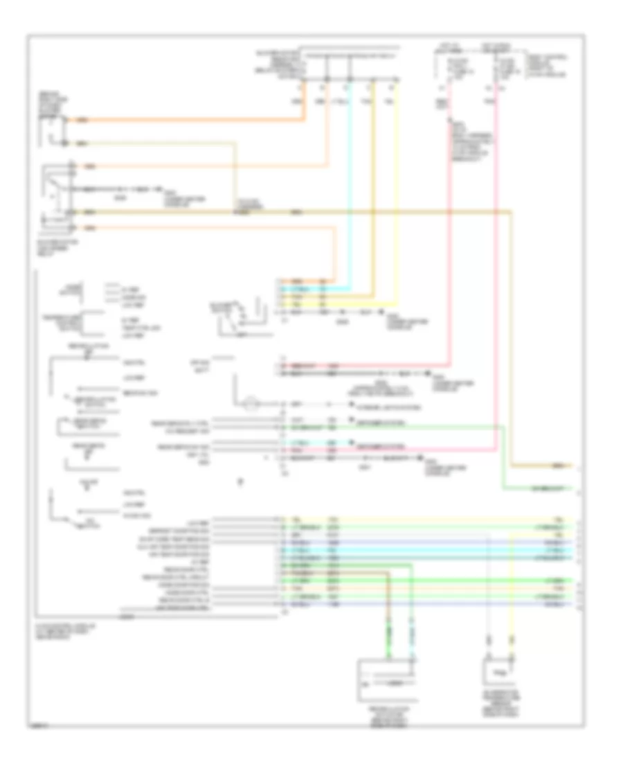
2.0L VIN M Turbo, Manual A/C Wiring Diagram (1 of 2) for Saturn Sky Red Line 2007
List of elements for 2.0L VIN M Turbo, Manual A/C Wiring Diagram (1 of 2) for Saturn Sky Red Line 2007:
- (behind right side of dash) blower motor
- (in hvac harness) s225
- 5v ref
- A/c ind
- A/c request sig
- A/c sw sig
- A/c switch
- Air temp door ctrl
- Air temp door pos sig
- Aux air temp door pos sig
- Batt
- Blower motor high speed relay
- Blower motor resistor assembly (below blower motor)
- Blower switch
- Body control module (right of hvac module)
- Defogger system
- Defrost door pos sig
- Evap core temp sens sig
- Evaporator temperature sensor (behind right side of dash)
- G300 (under center console)
- Gnd
- Hot at all times
- Hot in run or start
- Hvac control module (at center of dash, above radio)
- Hvac/ ip ign fuse 16 10a
- Hvac/ pk3 + fuse 10 10a
- Ign1 vol
- Ind ctrl
- Interior lights system
- Logic
- Low ref
- Mode door ctrl
- Mode door pos sig
- Mode sig
- Mode switch
- Off
- Off sig
- Pnk
- Rear defog ind
- Rear defog rly ctrl
- Rear defog sw sig
- Rear defog switch
- Recir door ctrl
- Recir door ctrl b
- Recir door ctrl circuit
- Recir sw sig
- Recirculation actuator (behind right side of dash)
- Recirculation ind
- Recirculation switch
- S203 (in i/p body harness, approximately 10 cm from hvac module breakout)
- S208 (approximately 8 cm from the ipc breakout)
- S226
- S301
- Tan
- Temp ctrl sig
- Temperature control switch
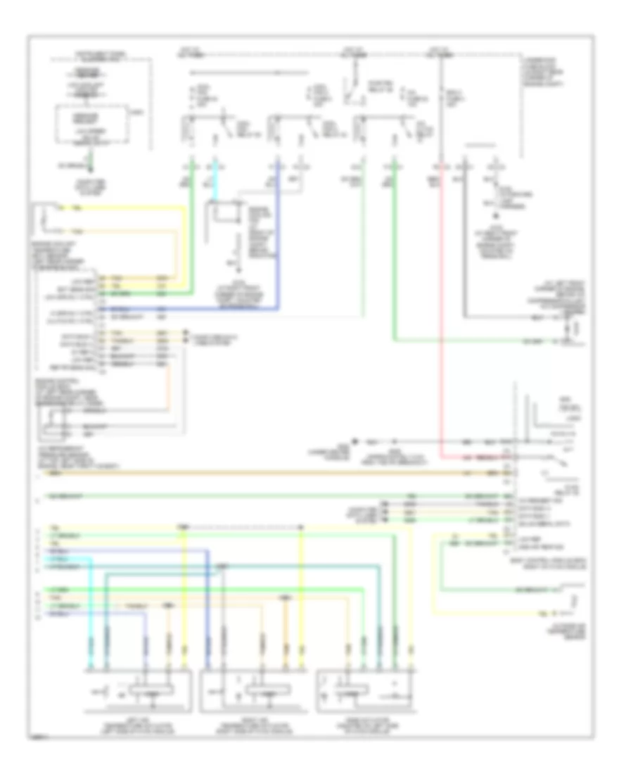
2.0L VIN M Turbo, Manual A/C Wiring Diagram (2 of 2) for Saturn Sky Red Line 2007
List of elements for 2.0L VIN M Turbo, Manual A/C Wiring Diagram (2 of 2) for Saturn Sky Red Line 2007:
- (approximately 10 cm from brake fluid level switch breakout) s110
- (at left front corner of engine, behind a/c compressor pulley) a/c compressor clutch
- (at top left side of engine, near throttle body) a/c refrigerant pressure sensor
- 5v ref 2
- A/c cltch relay
- A/c fuse 22 10a
- A/c ref pr sens sig
- A/c request sig
- Amb air temp sig
- Bcm 3 fuse 4 30a
- Body control module (bcm) (right of hvac module)
- Brake booster vacuum sensor (on brake vacuum booster)
- C1 b2
- C1 d3
- C1 f10
- C2 f6
- C3 c5
- C3 e1
- Clutch rly ctrl
- Computer data lines system
- Cooling fan spd ctrl
- Cooling fan speed control
- D10
- D12
- Data bus (+)
- Data bus (-)
- E12
- Ect sens sig
- Eng cool fan fuse 1 60a
- Engine control module (ecm) (at left rear corner of engine compt, near brake master cylinder)
- Engine coolant temperature (ect) sensor (left rear corner of engine block)
- Engine cooling fan (at front of engine compt, behind radiator)
- Fan sw
- G102 (at right front corner of engine compt, mounted on frame rail)
- G300 (under center console)
- Gmlan serial data
- Gnd
- Hot at all times
- Hvac relay 30
- Instrument panel cluster (ipc)
- Left air temperature actuator (left side of hvac module)
- Logic
- Low coolant cooling mode on
- Low ref
- Low speed gmlan serial data
- Message center
- Message request
- Mode actuator (mounted on left side of hvac module)
- Outside air temperature sensor
- Pwr/trn relay 26
- Right air temperature actuator (right side of hvac module)
- S102 (approximately 15 cm from brake fluid level switch breakout)
- S105 (in forward lamp harness)
- S111
- S112
- S113
- S114
- S208 (approximately 8 cm from the ipc breakout)
- Tan
- Underhood fuse block (in right rear corner of engine compt)
2.4L VIN B
2.4L VIN B, Manual A/C Wiring Diagram (1 of 2) for Saturn Sky Red Line 2007
List of elements for 2.4L VIN B, Manual A/C Wiring Diagram (1 of 2) for Saturn Sky Red Line 2007:
- (behind right side of dash) blower motor
- (in hvac harness) s225
- 5v ref
- A/c ind
- A/c request sig
- A/c sw sig
- A/c switch
- Air temp door ctrl
- Air temp door pos sig
- Aux air temp door pos sig
- Batt
- Blower motor high speed relay
- Blower motor resistor assembly (below blower motor)
- Blower switch
- Body control module (right of hvac module)
- Defogger system
- Defrost door pos sig
- Evap core temp sens sig
- Evaporator temperature sensor (behind right side of dash)
- G300 (under center console)
- Gnd
- Hot at all times
- Hot in run or start
- Hvac control module (at center of dash, above radio)
- Hvac/ ip ign fuse 16 10a
- Hvac/ pk3 + fuse 10 10a
- Ign1 vol
- Ind ctrl
- Interior lights system
- Logic
- Low ref
- Mode door ctrl
- Mode door pos sig
- Mode sig
- Mode switch
- Off
- Off sig
- Pnk
- Rear defog ind
- Rear defog rly ctrl
- Rear defog sw sig
- Rear defog switch
- Recir door ctrl
- Recir door ctrl b
- Recir door ctrl circuit
- Recir sw sig
- Recirculation actuator (behind right side of dash)
- Recirculation ind
- Recirculation switch
- S203 (in i/p body harness, approximately 10 cm from hvac module breakout)
- S208 (approximately 8 cm from the ipc breakout)
- S226
- S301
- Tan
- Temp ctrl sig
- Temperature control switch
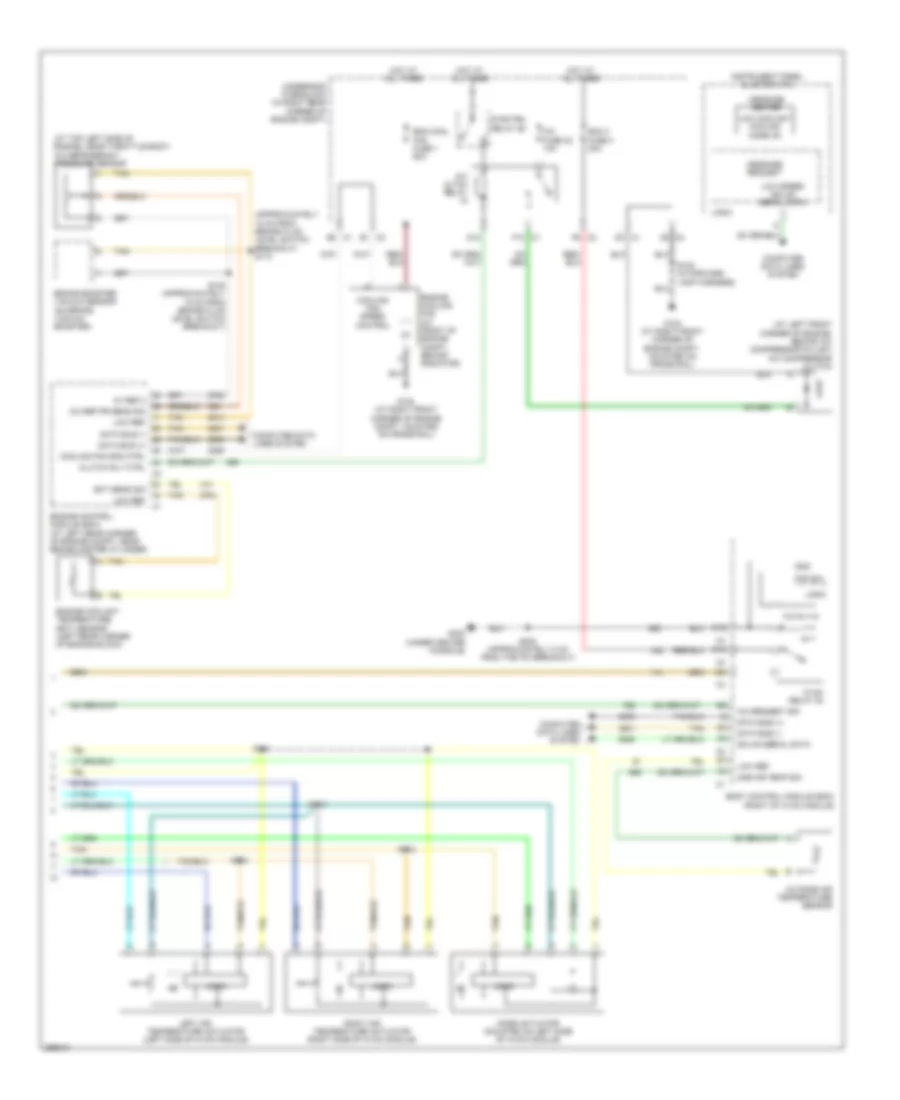
2.4L VIN B, Manual A/C Wiring Diagram (2 of 2) for Saturn Sky Red Line 2007
List of elements for 2.4L VIN B, Manual A/C Wiring Diagram (2 of 2) for Saturn Sky Red Line 2007:
- (at left front corner of engine, behind a/c compressor pulley) a/c compressor clutch
- 5v ref 2
- A/c cltch relay
- A/c fuse 22 10a
- A/c refrigerant pressure sensor (at top left side of engine, near throttle body)
- A/c request sig
- Amb air temp sig
- Bcm 3 fuse 4 30a
- Body control module (bcm) (right of hvac module)
- C1 a1
- C1 d3
- C1 f1
- C1 f10
- C2 f6
- C3 c5
- C3 e1
- C3 f4
- Clutch rly ctrl
- Computer data lines system
- Cool fan 2 fuse 8 30a
- Cool fan 2 relay 24
- Cool fan fuse 40 30a
- Cool fan relay 50
- D10
- D12
- Data bus (+)
- Data bus (-)
- E12
- Ect sens sig
- Engine control module (ecm) (at left rear corner of engine compt, near brake master cylinder)
- Engine coolant temperature (ect) sensor (left rear corner of engine block)
- Engine cooling fan (at front of engine compt, behind radiator)
- Fan sw
- G102 (at right front corner of engine compt, mounted on frame rail)
- G300 (under center console)
- Gmlan serial data
- Gnd
- Hi spd rly ctrl
- Hot at all times
- Hvac relay 30
- Instrument panel cluster (ipc)
- Left air temperature actuator (left side of hvac module)
- Logic
- Low coolant cooling mode on
- Low ref
- Low spd rly ctrl
- Low speed gmlan serial data
- Message center
- Message request
- Mode actuator (mounted on left side of hvac module)
- Outside air temperature sensor
- Pwr/trn relay 26
- Ref pr sens sig
- Right air temperature actuator (right side of hvac module)
- S105 (in forward lamp harness)
- S111
- S112
- S113
- S114
- S208 (approximately 8 cm from the ipc breakout)
- Tan
- Underhood fuse block (in right rear corner of engine compt)

 Dansk
Dansk Deutsch
 Ελληνικά
 English
 English
 Español
 Suomi
Suomi Français
 Français
 עברית
עברית Hrvatski
 Magyar
 Italiano
 日本語
日本語 한국어
한국어 Nederlands
 Polski
 Português
 Português
 Română
 Русский
 Slovenčina
 Slovenščina
 Svenska
 Türkçe
 中文 (中国)