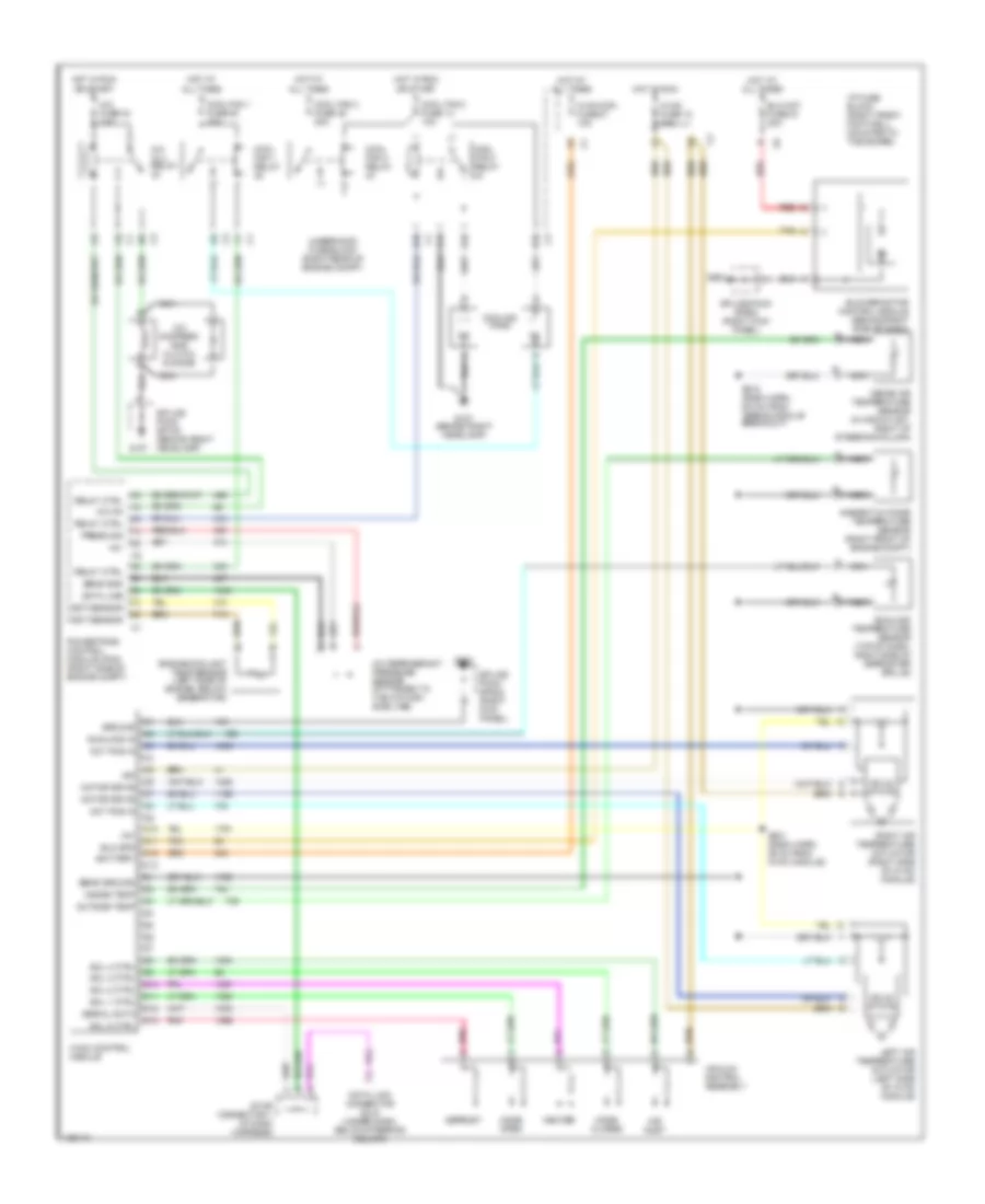
AIR CONDITIONING
Automatic A/C Wiring Diagram for Chevrolet Corvette 2000
List of elements for Automatic A/C Wiring Diagram for Chevrolet Corvette 2000:
- +5v
- A/c clu relay
- A/c compres- sor clutch & didoe
- A/c fuse 24 10a
- A/c on
- A/c refrigerant pressure sensor (attached to the a/c high side line)
- Act pos in
- Air inlet
- All times
- Ambient outside temperature sensor (right front of engine compt)
- Battery
- Blo mot fuse 51 30a
- Blo spd
- Blower motor control module (behind right side of dash)
- C10
- C11
- C12
- C13
- Cool fan 1 fuse 49 30a
- Cool fan 1 relay
- Cool fan 2 fuse 46 30a
- Cool fan 2 relay
- Cool fan 3 fuse 14 10a
- Cool fan 3 relay
- Cooling fans
- D10
- D11
- D12
- D13
- Data line
- Data link connector (dlc) (under dash, below steering column)
- Defrost
- E10
- Ect sensor
- Engine coolant temp sensor (left side of engine, below generator)
- F11
- G107
- G107 (behind right headlamp)
- G203
- Ground
- Heater
- Hot at
- Hot at all times
- Hot in run
- Hvac con fuse 27 10a
- Hvac control module
- Hvac fuse 18 10a
- I/p fuse block (right front footwell, mounted to toe board)
- Ign
- Inside air temperature sensor (in air outlet, right of steering column)
- Inside temp
- Left air temperature actuator (left side of hvac module)
- Mode closed
- Mode open
- Motor drive
- Nca
- Or start
- Outside temp
- Pnk
- Powertrain control module (pcm) (right side of engine compt)
- Press sig
- Red
- Relay ctrl
- Right air temperature actuator (right side of hvac module)
- S201 (dash harn, 35 cm from hvac module)
- S215 (dash harn, 6.5 cm from airbag module breakout)
- Sens gnd
- Sens ground
- Serial data
- Sol 1 ctrl
- Sol 2 ctrl
- Sol 3 ctrl
- Sol 4 ctrl
- Sol 5 ctrl
- Solid state
- Splice pack sp100 (behind right headlamp)
- Splice pack sp202 (right kick panel)
- Star connector 1 (in dash harness)
- Sunload in
- Sunload temperature sensor (top of dash, right side of defroster grille)
- Tan
- Underhood fuse block (right rear of engine compt)
- Vacuum control assembly
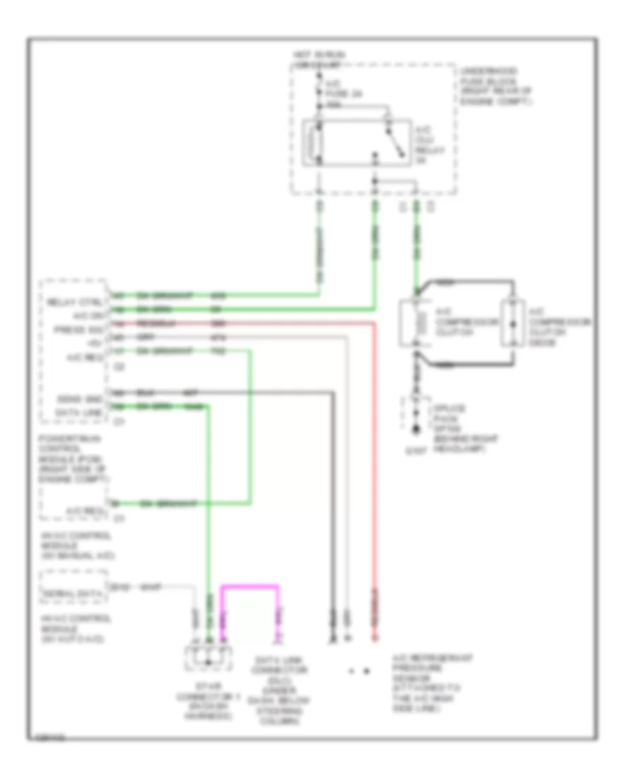
Compressor Wiring Diagram for Chevrolet Corvette 2000
List of elements for Compressor Wiring Diagram for Chevrolet Corvette 2000:
- +5v
- A/c clu relay
- A/c compressor clutch
- A/c compressor clutch didoe
- A/c fuse 24 10a
- A/c on
- A/c refrigerant pressure sensor (attached to the a/c high side line)
- A/c req
- D12
- Data line
- Data link connector (dlc) (under dash, below steering column)
- G107
- Hot in run or start
- Hvac control module (w/ auto a/c)
- Hvac control module (w/ manual a/c)
- Nca
- Powertrain control module (pcm) (right side of engine compt)
- Press sig
- Relay ctrl
- Sens gnd
- Serial data
- Splice pack sp100 (behind right headlamp)
- Star connector 1 (in dash harness)
- Underhood fuse block (right rear of engine compt)
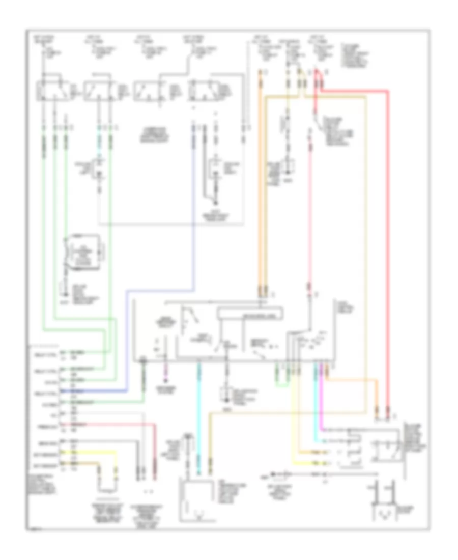
Manual A/C Wiring Diagram for Chevrolet Corvette 2000
List of elements for Manual A/C Wiring Diagram for Chevrolet Corvette 2000:
- +5v
- A/c clu relay
- A/c compres- sor clutch & didoe
- A/c fuse 24 10a
- A/c on
- A/c refrigerant pressure sensor (attached to the a/c high side line)
- A/c req
- Air recirc
- Air source logic
- Air temperature actuator (left side of hvac module)
- All times
- Blo mot maxi fuse 51 30a
- Blower motor
- Blower motor control module (behind right side of dash)
- Blower motor relay (on multi-use relay & fuse bracket, above bcm)
- Cool fan 1 fuse 49 30a
- Cool fan 1 relay
- Cool fan 2 fuse 46 30a
- Cool fan 2 relay
- Cool fan 3 fuse 14 10a
- Cool fan 3 relay
- Cooling fan (left)
- Cooling fan (right)
- D10
- Defogger system
- Defrost/ defog
- E10
- Ect sensor
- Engine coolant temp sensor (left side of engine, below generator)
- F11
- G tan
- G107
- G107 (behind right headlamp)
- G200
- G203
- Hot at
- Hot in run
- Hvac mini fuse 18 10a
- Hvac con mini fuse 27 10a
- Hvac control module
- I/p fuse block (right front footwell, mounted to toe board)
- Nca
- Off
- Or start
- Powertrain control module (pcm) (right side of engine compt)
- Press sig
- Rear defogger circuit
- Red
- Relay ctrl
- Sens gnd
- Splice pack sp100 (behind right headlamp)
- Splice pack sp201 (left kick panel)
- Splice pack sp202 (right kick panel)
- Tan
- Temp control
- Underhood fuse block (right rear of engine compt)

 Dansk
Dansk Deutsch
 Ελληνικά
 English
 English
 Español
 Suomi
Suomi Français
 Français
 עברית
עברית Hrvatski
 Magyar
 Italiano
 日本語
日本語 한국어
한국어 Nederlands
 Polski
 Português
 Português
 Română
 Русский
 Slovenčina
 Slovenščina
 Svenska
 Türkçe
 中文 (中国)