POWER DISTRIBUTION
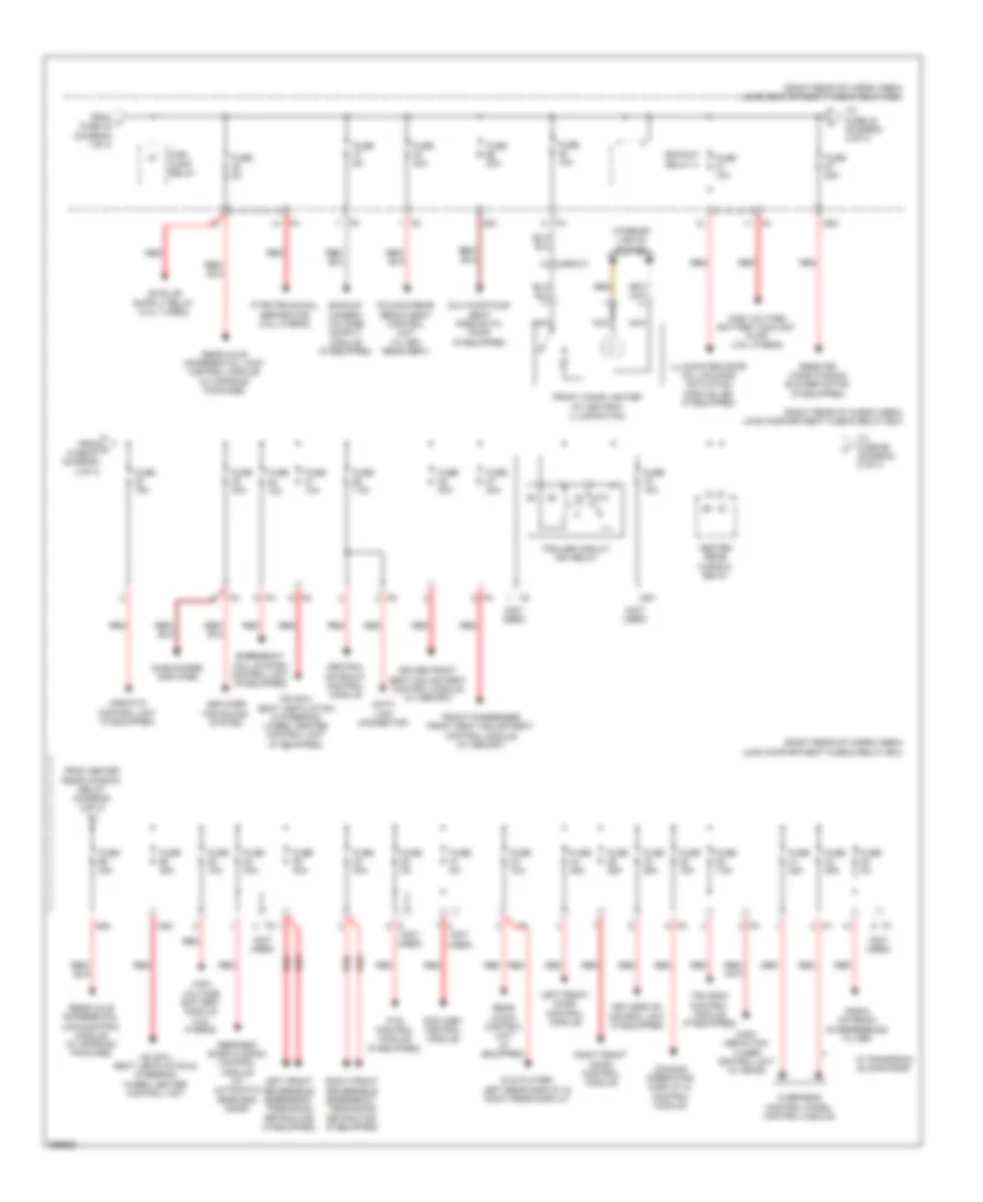
Power Distribution Wiring Diagram (1 of 4) for Mercedes-Benz ML350 4Matic 2011
 https://portal-diagnostov.com/license.html
Automotive Electricians Portal FZCO
Automotive Electricians Portal FZCO
https://portal-diagnostov.com/license.html
https://portal-diagnostov.com/license.html
Automotive Electricians Portal FZCO
Automotive Electricians Portal FZCO
List of elements for Power Distribution Wiring Diagram (1 of 4) for Mercedes-Benz ML350 4Matic 2011:
- (at right "d" pillar) (gl-class) w7
- (right rear of cargo area) load compartment fuse & relay box
- (under right rear seat) (ml-class) w17
- 3.0l turbo diesel
- 3.5l hybrid
- 87a
- Ac air recirculation unit
- Activated charcoal filter shutoff valve (except 3.0l turbo & 3.5l hybrid)
- Backup camera (if equipped)
- Battery
- Battery compartment prefuse box (under right front seat)
- C78
- C79
- C80
- C81
- C82
- C83
- C84
- C85
- C86
- C87
- C88
- C89
- C90
- C91
- Circuit 15r 2/ spare 1 relay (change over contact)
- Circuit 15r relay
- Circuit 31 right rear seat voltage distributor coonnector (ml-class) circuit 31 right wheel house luggage compartment voltage distributor connector (gl-class)
- Circuit relay/spare1 relay (change over contact)
- Driver lumbar support regulator control unit (if equipped)
- Driver neck- pro head restraint solenoid (w/ crash active head restraints)
- Driver seat adjustment switch (if equipped)
- Emergency call system control unit (if equipped)
- Front interior socket
- Front passenger lumbar support regulator control unit (if equipped)
- Front passenger neck-pro head restraint solenoid (w/ crash active head restraints)
- Front passenger seat adjustment switch (if equipped)
- Front sam control unit
- Fuel pump control module (except 3.0l turbo)
- Fuse 100a
- Fuse 10a
- Fuse 150a 40a
- Fuse 15a
- Fuse 20a
- Fuse 30a
- Fuse 40a
- Fuse 5a
- Fuse 60a
- Fuse 7.5a
- Fuse 70a
- Gl- class
- Glove compartment illumination w/ switch
- Hybrid vehicle fully integrated transmission control controller unit
- Instrument cluster & rotary light switch
- Left rear bumper intelligent radar sensor & right rear bumper intelligent radar sensor (early production)
- Left rear bumper intelligent radar sensor & right rear bumper intelligent radar sensor (late production)
- Load compartment socket
- Ml-class
- Multicontour seat pneumatic pump (if equipped)
- Pnk
- Ptc heater booster (if equipped)
- Pyrotechnical separator
- Rear sam control module
- Rear sam control module & front sam control module
- Rear wiper relay
- Red
- Restraint systems control module
- Right 2nd seat row socket
- Socket circuit 15r relay (w/ run-on)
- Spare 2 relay (normally open contact)
- Tailgate wiper motor
- To 115v socket (diagram 3 of 4)
- To cockpit fuse box (diagram 4 of 4)
- To dc/ac converter control unit (115v socket) (diagram 3 of 4)
- To engine compartment fuse & relay box (diagram 3 of 4)
- To engine compartment fuse & relay box (diagram 4 of 4)
- To engine compartment fuse & relay box 2 (diagram 4 of 4)
- To front prefuse (diagram 3 of 4)
- To fuse (diagram 3 of 4)
- To fuse pump relay (diagram 2 of 4)
- Trailer circuit 30 relay
- Transfer case control unit
- Vacuum pump relay (+)
- W/ full hybrid drive
- W/ offroad package
- W15/1 (under right front footwell)
- W29/2 (at right kick panel)
- W6/6 (gl-class) (left rear of cargo area floor)
- W7 (ml-class) (behind trim, right rear of cargo area)
- Wss control unit (weight sensing system)
- X18-c2
- X25/2-c1 a5
- X25/2-c2 d4
- X25/2-c2 h2
- X29/6-c1
- X2916-c1
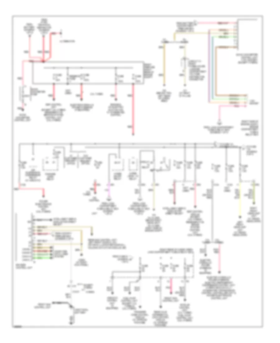
Power Distribution Wiring Diagram (2 of 4) for Mercedes-Benz ML350 4Matic 2011
List of elements for Power Distribution Wiring Diagram (2 of 4) for Mercedes-Benz ML350 4Matic 2011:
- (not used)
- (right rear of cargo area) load compartment fuse & relay box
- 87a
- Airmatic control unit (if equipped)
- Amplifier for sound system
- Backup relay 2
- Central gateway control module
- Comand operating, display & control module
- Data link connector
- Driver front seat adjustment control module (w/ memory)
- Dvd player, left rear display & right rear display
- Emergency call system control unit (if equipped)
- Folding rear bench seat control unit (w/ 3rd rear seat)
- From h fuse 43 (diagram 1 0f 4)
- From heated rear window relay (diagram 2 of 4)
- From j fuse 67 (diagram 2 0f 4)
- Front cigar lighter (w/ ashtray illumination)
- Front passenger front seat adjustment control module (w/ memory)
- Fuel pump relay
- Fuse 10a
- Fuse 15a
- Fuse 25a
- Fuse 30a
- Fuse 40a
- Fuse 5a
- Fuse 7.5a
- Heated rear window relay
- High voltage battery coolant pump (3.5l hybrid)
- High voltage battery module (3.5l hybrid)
- High- definition tuner control unit (w/ sdar)
- Hs (sih), seat ventilation & steering wheel heater control unit
- Hs (sih), seat ventilation & steering wheel heater control unit (if equipped)
- Illuminated door sill molding actuation module led (if equipped)
- Interior lights system
- Keyless go control unit (if equipped)
- Left front door control module
- Left front reversible emergency tensioning retractor (if equipped)
- Ms1
- Ms2
- Ms3
- Ms4
- Ms7
- Multicontour seat pneumatic pump (if equipped)
- Nca
- Overhead control panel control module
- Pts control module (if equipped)
- Pyrotechnical separator (3.5l hybrid)
- Radio antenna interference filter
- Rcp (hbf) control module
- Rear air conditioning blower motor (if equipped)
- Rear audio control unit (if equipped)
- Rear axle differential lock control module (w/ offroad package)
- Rear-end door closing control module (w/ automatic rear end door)
- Red
- Right front door control module
- Right front reversible emergency tensioning retractor (if equipped)
- Subwoofer amplifier
- To fuse 32 (diagram 2 of 4)
- To fuse 69 (diagram 2 of 4)
- Tpm (rdk) control module (if equipped)
- Trailer circuit 30x relay
- W/ panoromic sliding roof
- X29/6-c1
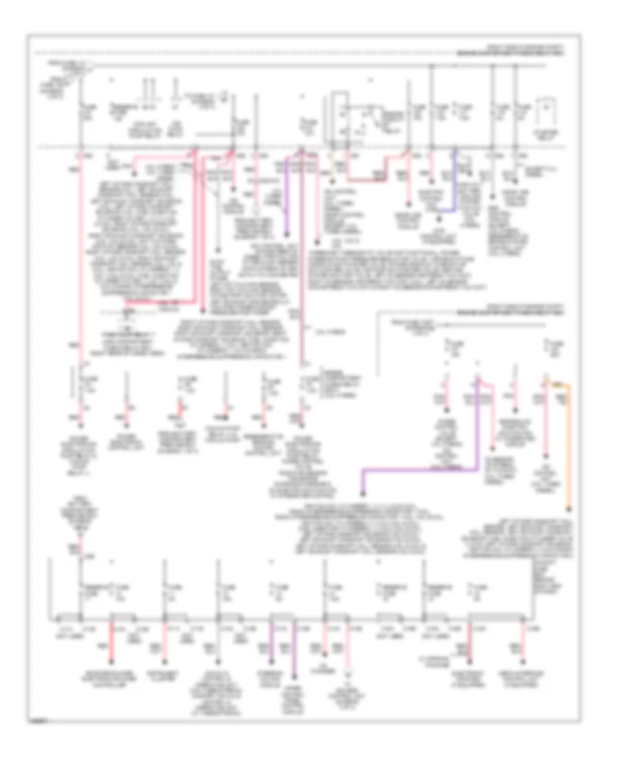
Power Distribution Wiring Diagram (3 of 4) for Mercedes-Benz ML350 4Matic 2011
List of elements for Power Distribution Wiring Diagram (3 of 4) for Mercedes-Benz ML350 4Matic 2011:
- (not used)
- (right rear of cargo area) load compartment fuse & relay box
- (right side of engine compt) engine compartment fuse & relay box
- (w/ airmatic)
- 115v socket
- 3.0l turbo
- 3.5l hybrid
- 300a
- Additional battery
- Air suspension compressor relay
- Airmatic control unit (if equipped)
- Alternator
- C123
- C124
- C125
- Can-b h
- Can-b l
- Can-c h
- Can-c l
- Cdi control
- Circuit
- Circuit 31 right wheelhouse luggage compartment voltage distributor connector
- Computer data lines system
- Dc/ac converter control unit (115v socket) (except hybrid)
- Dc/dc converter control unit
- Dc/dc converter fuse
- Eis (ezs) control unit
- Electro hydraulic power steering (if equipped)
- Electro hydraulic power steering, electric refrigerant compressor control unit, hybrid vehicle fully integrated transmission control controller unit & power electronics control unit
- Electrohydraulic power steering (if equipped)
- Engine & ac electric suction fan w/ integrated control
- Esp control module (except 3.5l hybrid) regenerative brake system control unit (3.5l hybrid)
- Esp control unit (except 3.5l hybrid) regenerative braking system control unit (3.5l hybrid)
- Except hybrid
- Fanfare horn relay
- From battery (diagram 1 of 4)
- From battery c compartment prefuse box (diagram 1 0f 4)
- From cockpit prefuse box (diagram 4 of 4)
- From fuse 51 (diagram r 1 of 4)
- From load compartment fuse & relay box (diagram 1 0f 4)
- From load compartment fuse & relay box (diagram 1 of 4)
- From pyro- technical separator (diagram 1 of 4)
- Front prefuse (right rear of engine compt)
- Front sam control unit
- Fuel pump control unit (except 3.0l turbo & 3.5l hybrid)
- Fuse 100a
- Fuse 10a
- Fuse 15a
- Fuse 25a
- Fuse 30a
- Fuse 40a
- Fuse 5a
- Fuse 7.5a
- Gl- class
- Hybrid
- Intelligent servo module for direct select
- Ism
- Left front headlamp unit (w/ xenon headlamps)
- Ml- class
- Mr1
- Mr3
- Mr4
- Nca
- Pnk
- Pnk/ red
- Power electronics control unit (3.5l hybrid)
- Rear axle differential lock control module (w/ offroad package)
- Rear sam control unit, left front door cl (zv) motor & illuminated door sill molding actuation module led
- Red
- Relay
- Reserve fuse
- Right front headlamp unit (w/ xenon headlamps)
- To fuse (diagram 4 of 4)
- To fuse 121 (diagram 4 of 4)
- Transfer case control module (w/ offroad package)
- Unit
- W/ customer request option
- W/o customer request option
- W2 (ml-class: behind right headlight) (gl class: right side of engine compt)
- W29/2 (at right kick panel)
- W6 (behind trim, left rear of cargo area)
- W7 (at right "d" pillar)
- Wiper level 1/2 relay
- Wiper on/off relay
- X18
- X18-c1
Power Distribution Wiring Diagram (4 of 4) for Mercedes-Benz ML350 4Matic 2011
List of elements for Power Distribution Wiring Diagram (4 of 4) for Mercedes-Benz ML350 4Matic 2011:
- (not used)
- (right side of engine compt) engine compartment fuse & relay box
- 3.0l turbo diesel
- 3.5l hybrid
- 3.5l hybrid 3.0l turbo diesel
- 3.5l, 4.6l & 5.5l
- Acc (kla) control & operating unit (w/o thermotronic) comfort acc (kla) control & operating unit (w/ thermotronic)
- Air pump relay
- Booster blower electronic blower controller
- C10a
- C10b
- C11a
- C11b
- C12a
- C12b
- C13a
- C13b
- C14a
- C14b
- C15a
- C15b
- C16a
- C16b
- C17a
- C17b
- C18a
- C18b
- C5e
- Cd changer
- Cdi control module
- Cdi control unit (3.0l turbo diesel) me-sfi control module (except 3.0l turbo diesel)
- Cdi control unit (3.5l turbo diesel)
- Cockpit fuse box (behind right end of dash)
- Coolant circulation pump relay
- Dtr control unit (if equipped)
- Electric control unit (vgs)
- Electronic compass (if equipped)
- Engine & ac electric suction fan w/ integrated module
- Engine circuit relay
- Engine compartment fuse & relay box 2 (3.5l hybrid)
- Esp control module (except 3.5l hybrid) regenerative brake system control unit (3.5l hybrid)
- Except 3.0l diesel
- From battery compartment prefuse box (diagram 1 of 4)
- From fuse 105 (diagram o 4 of 4)
- From fuse 112 (diagram m 3 of 4)
- From l fuse 109 (diagram 3 of 4)
- Fuel pump relay
- Fuse 10a
- Fuse 15a
- Fuse 20a
- Fuse 5a
- Fuse 7.5a
- Fuse fa 7.5a
- Fuse fb 7.5a
- Fuse fc 7.5a
- Fuse fd 7.5a
- G1 x25/2-c2
- Glow time output stage, left hot film maf sensor, right hot film maf sensor, intake port shutoff motor, left exhaust gas recircula- tion positioner & boost pressure positioner
- High-volt battery cooling system two-way valve (3.5l hybrid)
- Ignition coil cylinders 1, 2, 3, 4, 5 & 6 (3.5l), radio interference suppression capacitor 1 (3.5l), radio interference suppression capacitor 1 (3.5l, 4.6l & 5.5l), ignition coil cylinders 2, 3, 5 & 8 (4.6l & 5.5l), fuel ingector cylinder's 2, 3, 5 & 8 (4.6l & 5.5l), left intake camshaft solenoid (4.6l & 5.5l), left exhaust camshaft solenoid (4.6l & 5.5l), left intake camshaft hall sensor (4.6l & 5.5l) & left exhaust camshaft hall sensor (4.6l & 5.5l)
- Instrument cluster
- Left intake camshaft hall sensor (3.5l), left exhaust camshaft hall sensor (3.5l), left exhaust camshaft solenoid (3.5l), left intake camshaft solenoid (3.5l), fuel injection cylinder valves 1, 2, 3, 4, 5 & 6 (3.5l), right intake camshaft solenoid (3.5l, 4.6l & 5.5l), right exhaust camshaft solenoid (3.5l, 4.6l & 5.5l), hot film mass air flow sensor (3.5l, 4.6l & 5.5l), right intake camshaft hall sensor (3.5l, 4.6l & 5.5l), right exhaust camshaft hall sensor (3.5l, 4.6l & 5.5l), igntion coil cylinder's 1, 4, 6 & 7 (4.6l & 5.5l), fuel injection cylinder valves 1, 4 & 7 (4.6l & 5.5l) & radio interference suppression capacitor 1 (4.6l & 5.5l)
- Left intake camshaft hall sensor, left exhaust camshaft hall sensor, left exhaust camshaft solenoid, fuel injection cylinder valve 4, 5 & 6, left intake camshaft solenoid, ignition coil cylinder's 4, 5 & 6 & radio interference suppression capacitor 2
- Load compartment fuse & relay box (right rear of cargo area)
- Me-sfi (me) control module
- Media interface control unit (if equipped)
- Mr1
- Mr2
- Mr3
- Mr4
- Nox control unit downstream of diesel particulate filter & nox sensor down stream of scr catalytic converter
- O2 sensor up stream of twc(kat) (3.0l turbo diesel)
- Pnk
- Power electronic control unit
- Power electronics circulation pump relay & vaccum pump relay (-)
- Power electronics circulation pump relay, purge control valve, radiator sensor for engine diagnosis & engine & ac electric suction fan w/ integrated control
- Purge control valve (except 3.5l hybrid) cdi control unit (3.5l hybrid)
- Red
- Regenerative braking system control unit
- Reserve fuse
- Right intake camshaft hall sensor, right exhaust camshaft hall sensor, right exhaust camshaft solenoid, right intake camshaft soleniod, fuel injection cylinder's 1, 2 & 3, ignition coil cylinder's 1, 2 & 3 & radio interference suppression capacitor 1
- Starter relay
- Steering column module
- Three-disk thermostat valve (not functional), power steering pump pressure regulator valve, variable intake manifold switchover valve, intake manifold tumble flap switchover valve, air pump switchover valve, heating system shutoff valve, left o2 sensor upstream twc (kat), right o2 sensor upstream twc (kat) (3.5l), left o2 sensor downstream twc (kat) & right o2 sensor downstream twc (kat)
- To eis (ezs) control unit (diagram 3 of 4)
- To fuse 101 (diagram 4 of 4)
- Upper control panel control module
- Vacuum pump relay (+) & vacuum pump
- W/ offroad package
- X25/2-c2

 Dansk
Dansk Deutsch
 Ελληνικά
 English
 English
 Español
 Suomi
Suomi Français
 Français
 עברית
עברית Hrvatski
 Magyar
 Italiano
 日本語
日本語 한국어
한국어 Nederlands
 Polski
 Português
 Português
 Română
 Русский
 Slovenčina
 Slovenščina
 Svenska
 Türkçe
 中文 (中国)