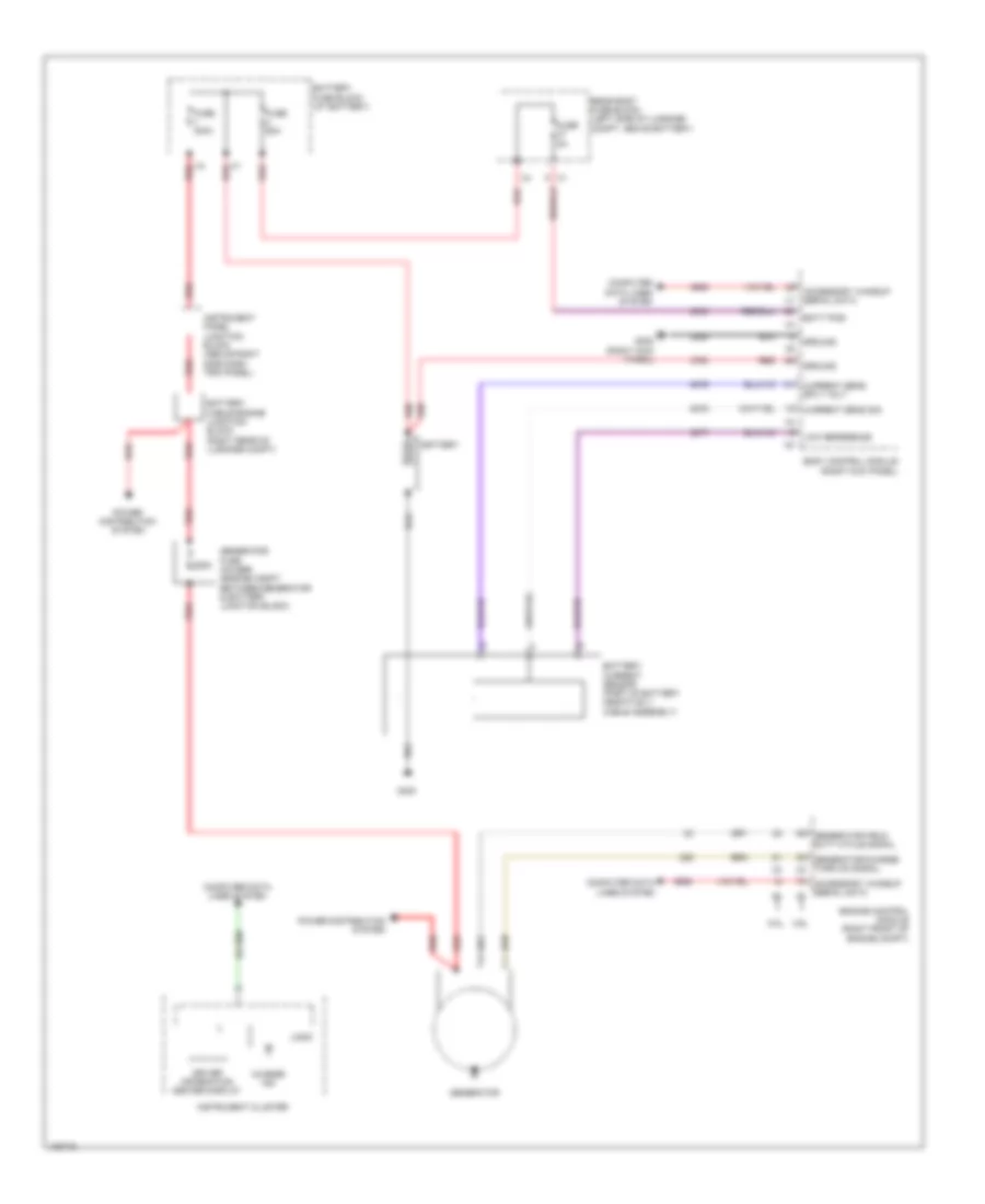
STARTING/CHARGING
Charging Wiring Diagram for Chevrolet Caprice PPV 2014
List of elements for Charging Wiring Diagram for Chevrolet Caprice PPV 2014:
- 225a
- 3.6l
- 6.0l
- Accessory wakeup serial data x1
- Batt posi
- Battery
- Battery cable engine junction block (right rear of luggage compt)
- Battery fuse block (at battery)
- Body control module (right kick panel)
- Charge ind
- Computer data lines system
- Current sens sig
- Current sens sply volt
- Driver information center display
- Engine control module (right front of engine compt)
- Fuse 300a
- Fuse 5a
- Fuse 60a
- G302 (right kick panel)
- G400
- Generator
- Generator field duty cycle signal
- Generator fuse holder (engine compt between generator & battery junction block)
- Generator/charge turn on signal x2
- Ground
- Instrument cluster
- Instrument panel junction block (above right side dash trim panel)
- Logic
- Low reference
- Power distribution system
- Rear body fuse block (left side of luggage compt, above battery)
- Red
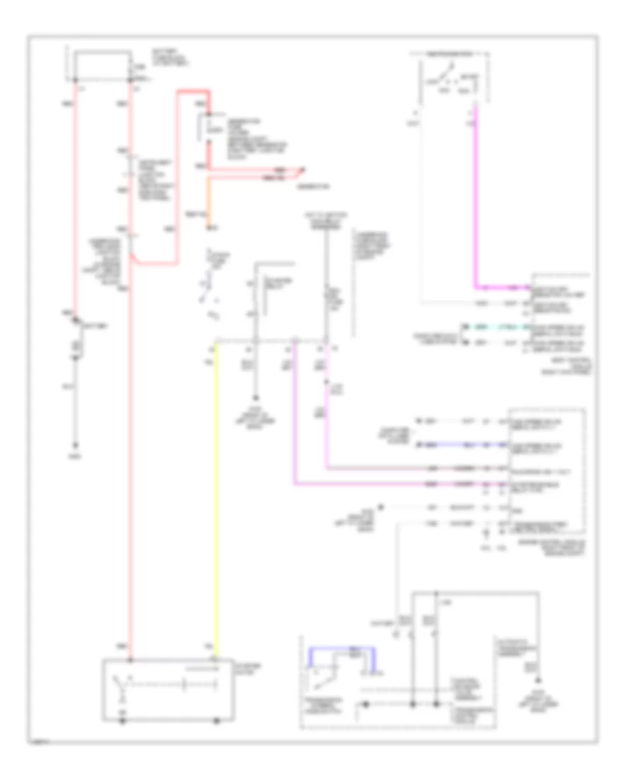
Starting Wiring Diagram for Chevrolet Caprice PPV 2014
List of elements for Starting Wiring Diagram for Chevrolet Caprice PPV 2014:
- 225a
- 3.6l
- 6.0l
- Acc
- Automatic transmission assembly
- Battery
- Battery fuse block (at battery)
- Body control module (right kick panel)
- Computer data lines system
- Control solenoid valve assembly
- Ecm ign fuse 15a
- Engine control module (right front of engine compt)
- Fise 300a
- G100 (front of left cylinder bank)
- G400
- Generator
- Generator fuse holder (engine compt between generator & battery junction block)
- Gnd
- High speed gmlan serial data (+) 1
- High speed gmlan serial data (-) 1
- High speed gmlan serial data bus+
- High speed gmlan serial data bus- x1
- Hot w/ ignition main relay energized
- Ignition key resistor low ref
- Ignition key resistor sig
- Ignition switch
- Instrument panel junction block (above right side dash trim panel)
- J116 (6.0l)
- J125
- Lock
- Red
- Run
- Run/crank ign 1 volt
- Start
- Starter enable relay ctrl
- Starter motor
- Starter relay
- Strtr fuse 30a
- Transmission control module
- Transmission internal mode switch
- Transmission park/ neutral signal 1
- Underhood fuse block (right front of engine compt)
- Underhood provision junction block (in engine compt, above junction block)

 Dansk
Dansk Deutsch
 Ελληνικά
 English
 English
 Español
 Suomi
Suomi Français
 Français
 עברית
עברית Hrvatski
 Magyar
 Italiano
 日本語
日本語 한국어
한국어 Nederlands
 Polski
 Português
 Português
 Română
 Русский
 Slovenčina
 Slovenščina
 Svenska
 Türkçe
 中文 (中国)