TRANSMISSION
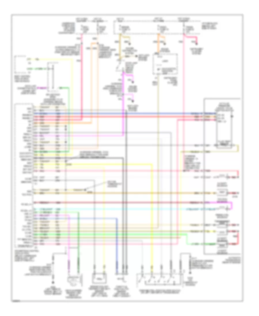
A/T Wiring Diagram for Chevrolet Astro 2005
List of elements for A/T Wiring Diagram for Chevrolet Astro 2005:
- (in engine harness, 15 cm from underhood fuse block breakout) s112
- (in engine harness, 18 cm from breakout for mass airflow, toward c100)
- (in engine harness, 18 cm from breakout for mass airflow, toward c100) s115
- (on the thermostat housing)
- +5v
- 1-2 shift solenoid
- 1-2 ss
- 2-3 shift solenoid
- 2-3 ss
- 3-2 shift solenoid
- 3-2 ss
- A/t fluid pressure manual valve position switch
- A12
- Anti-lock brakes system
- Automatic transmission (rear of engine)
- Body control module (bcm) (above radio)
- Brake fuse 18 10a
- Brk sw
- Cls 2 data
- Cruise control system
- D3, d2
- D4, d2
- Data link connector (dlc) (under left side of dash)
- Ecm b fuse 20a
- Ecm i fuse 20a
- Ect sig
- Engine coolant temperature (ect) sensor (left side of left cyl head)
- Fluid temp sensor
- G105
- G105 (on thermostat housing)
- G106 (left rear of engine, next to knock sensor)
- Gnd
- Harness, near underhood fuse block breakout)
- Hot at all times
- Hot in run
- Hot in run & start
- I/p fuse block (behind left side of dash)
- Ign
- Ignition
- Instrument cluster system
- Instrument panel cluster (ipc)
- Lo ref
- Logic
- Malfunction indicator lamp
- Mil ctrl
- Park/neutral position (pnp) switch (on left center of transmission)
- Pc sol hi
- Pc sol lo
- Pnk
- Power distribution system
- Powertrain control module (pcm) (below underhood fuse block, left side of firewall)
- Press ctrl solenoid
- Prnd a
- Prnd b
- Prnd c
- Prnd p
- Radio fuse 19 10a
- Range b
- Range c
- Red
- Red a
- Red b
- Rev, lo
- S116 (in engine harness, 16 cm from breakout to mass airflow sensor, behind battery)
- S117 (in engine harness, near a/c low pressure cut-off switch breakout)
- S127 (in engine harness, near park/neutral position & backup lamp switch breakout)
- S135
- S155
- Sens gnd
- Sound systems
- Splice pack sp261 (strapped to i/p harness, behind data link connector)
- Stop lamp switch (above brake pedal)
- Tan
- Tcc pwm
- Tcc pwm solenoid
- Tcc sol
- Tcc solenoid
- Tft sens sig
- Throttle position (tp) sensor (left side of throttle body)
- Tp sig
- Trans fuse 20 10a
- Trans rng a
- Underhood fuse block (left side of engine compartment)
- Vehicle speed sensor (vss) (rear of transmission)
- Vss hi
- Vss lo
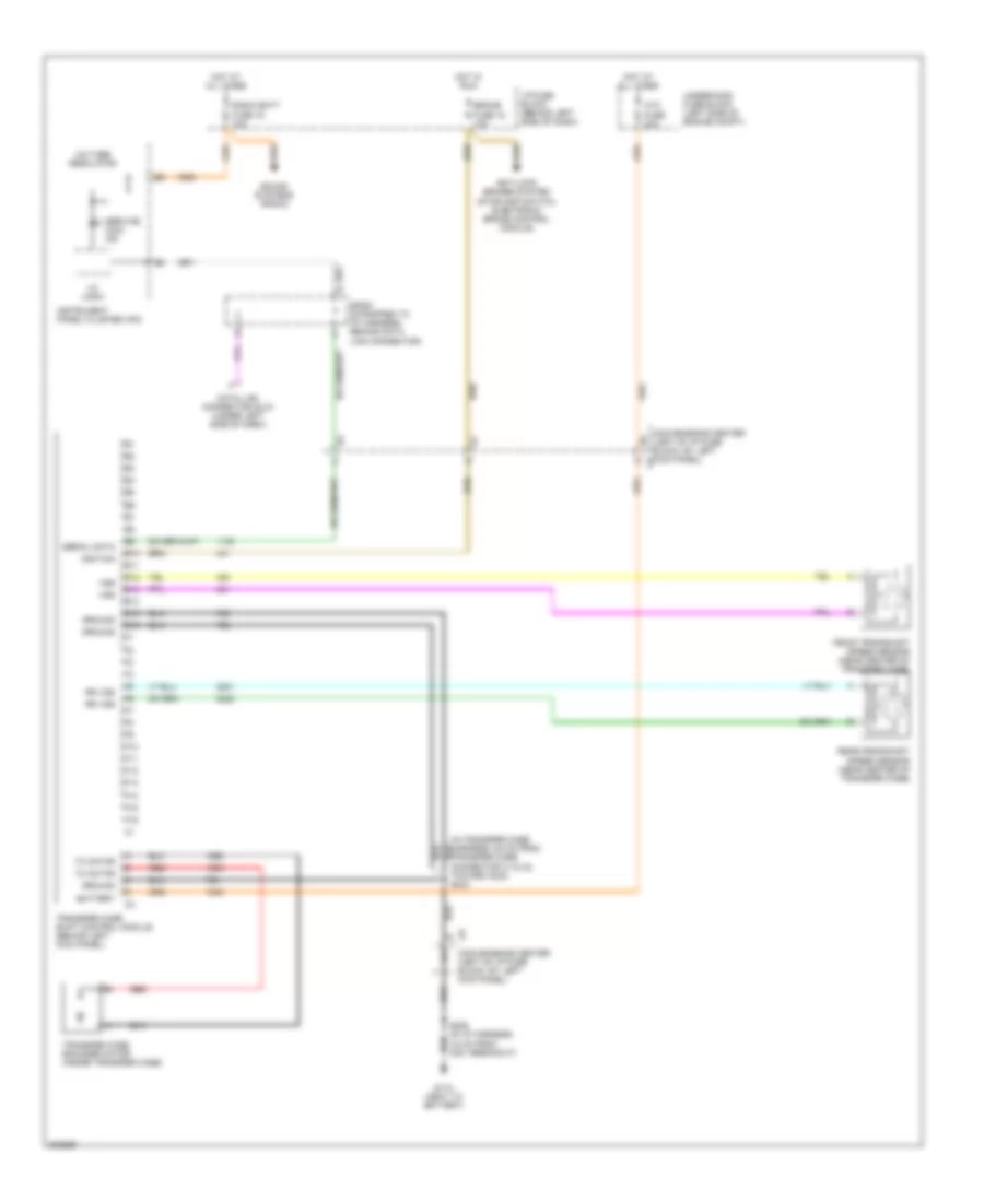
Transfer Case Wiring Diagram for Chevrolet Astro 2005
List of elements for Transfer Case Wiring Diagram for Chevrolet Astro 2005:
- (in transfer case harness, 6.5 cm from transfer case connector c1 & c2, toward c224) s243
- Anti-lock brakes system (stoplamp switch, electronic brake control module)
- Atc
- Battery
- Brake
- C8 convenience center (left of i/p fuse block, by left kick panel)
- Convenience center (left of i/p fuse block, by left kick panel)
- Data link connector (dlc) (under left side of dash)
- E10
- E11
- E12
- E13
- E14
- E15
- E16
- F10
- F11
- F12
- F13
- F14
- F15
- F16
- Front propshaft speed sensor (near center of transfer case)
- Fuse 18 10a
- Fuse 20a
- G110 (next to battery)
- Ground
- Hot at all times
- Hot in run
- I/c logic
- I/p fuse block (behind left side of dash)
- Ignition
- Instrument panel cluster (ipc)
- Radio batt fuse 19 10a
- Rear propshaft speed sensor (near center of transfer case)
- Red
- Rr vss
- S206 (in i/p harness, 3.5 cm from c201 breakout)
- Serial data
- Service awd ind
- Sound systems (radio)
- Sp261 (strapped to i/p harness, behind data link connector)
- Tc motor
- Transfer case encoder motor (inside transfer case)
- Transfer case shift control module (behind left kick panel)
- Underhood fuse block (left side of engine compt)
- Voltage regulator
- Vss

 Dansk
Dansk Deutsch
 Ελληνικά
 English
 English
 Español
 Suomi
Suomi Français
 Français
 עברית
עברית Hrvatski
 Magyar
 Italiano
 日本語
日本語 한국어
한국어 Nederlands
 Polski
 Português
 Português
 Română
 Русский
 Slovenčina
 Slovenščina
 Svenska
 Türkçe
 中文 (中国)