Diagram sections — 29 (46 total)
ANTI-LOCK BRAKES ANTI-THEFT COMPUTER DATA LINES CRUISE CONTROL DEFOGGERS ELECTRONIC POWER STEERING ELECTRONIC SUSPENSION ENGINE PERFORMANCE EXTERIOR LIGHTS GROUND DISTRIBUTION HEADLIGHTS HORN INSTRUMENT CLUSTER INTERIOR LIGHTS POWER ANTENNA POWER DISTRIBUTION POWER DOOR LOCKS POWER MIRRORS POWER SEATS POWER TOP/SUNROOF POWER WINDOWS RADIO SHIFT INTERLOCKS STARTING/CHARGING SUPPLEMENTAL RESTRAINTS TRANSMISSION TRUNK, TAILGATE, FUEL DOOR WARNING SYSTEMS WIPER/WASHER
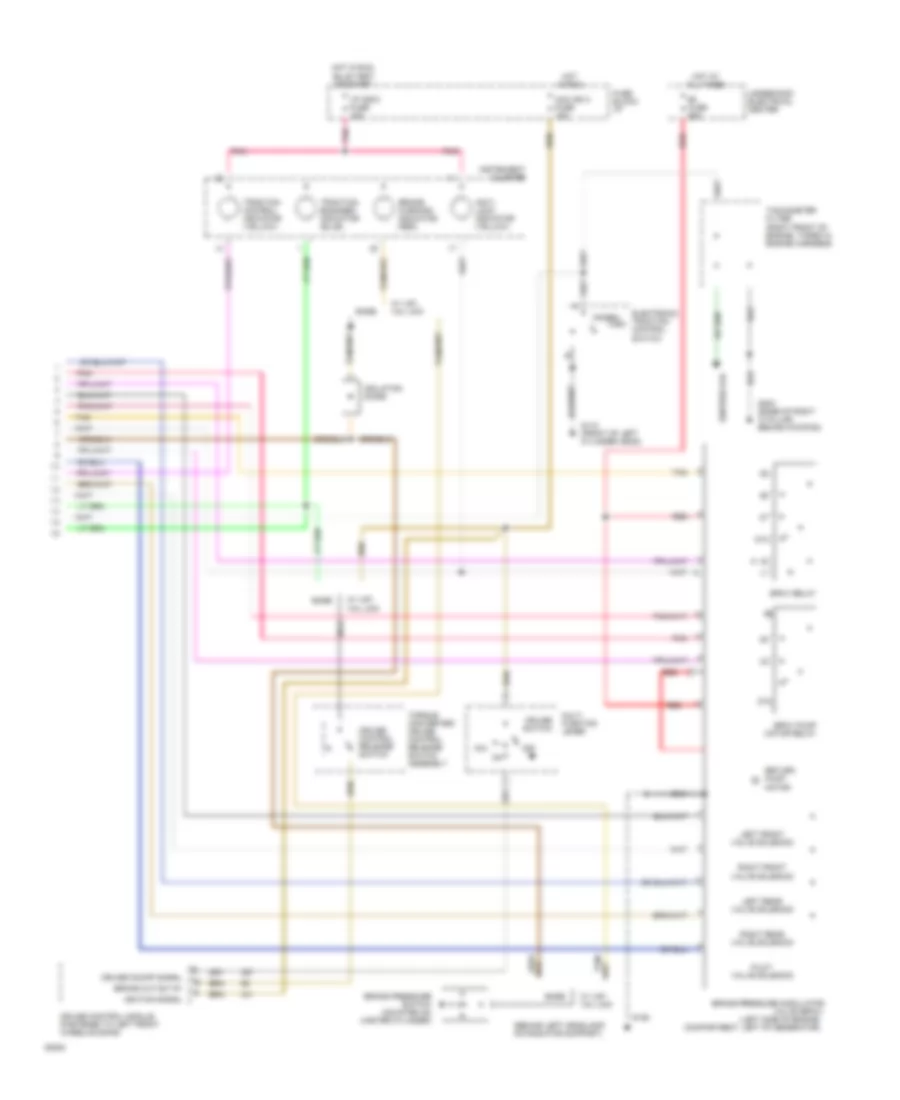
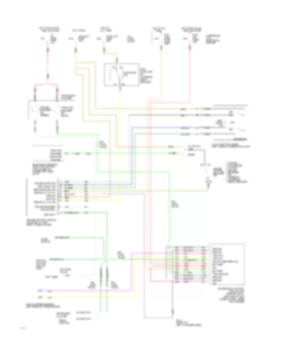
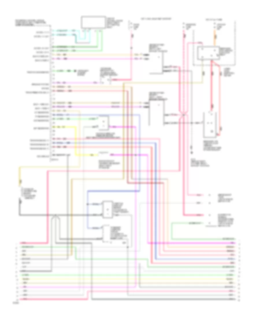
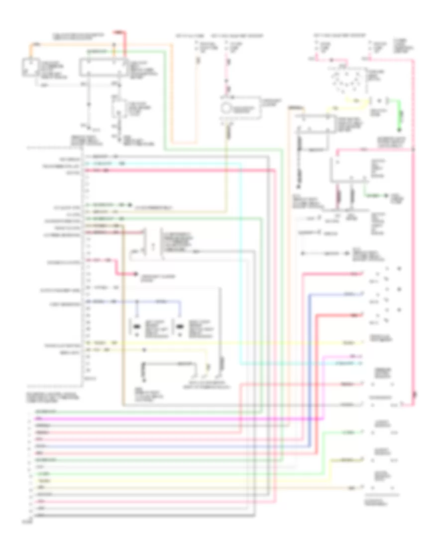
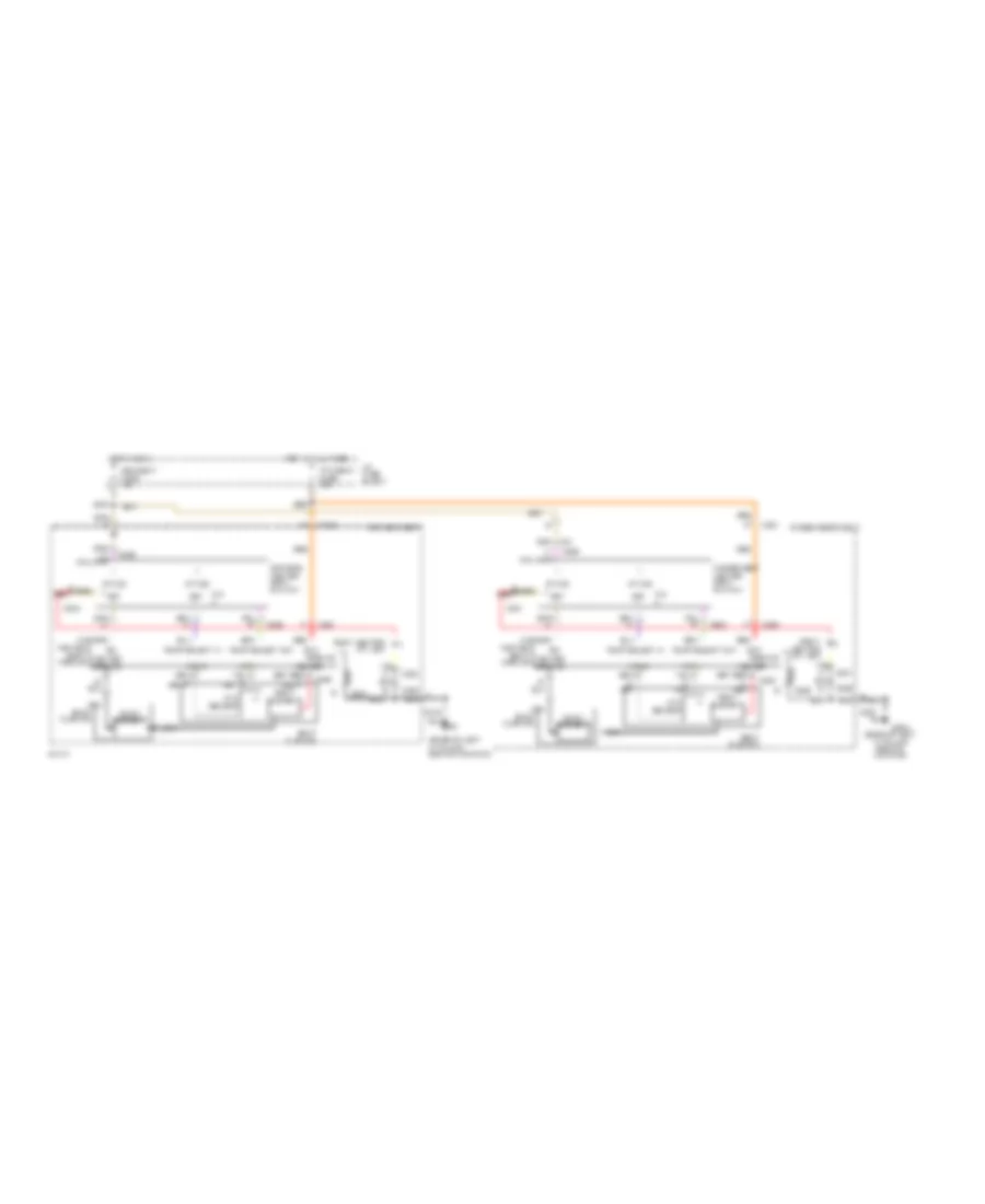
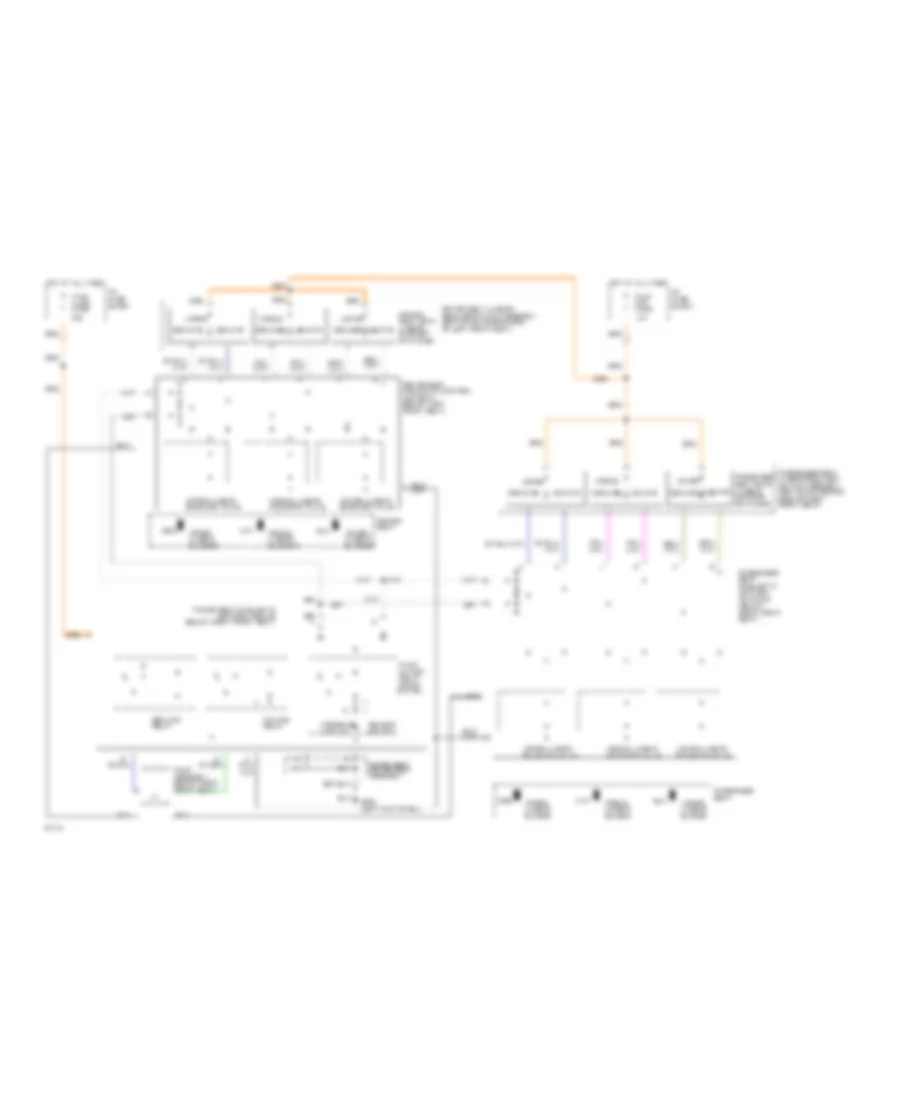
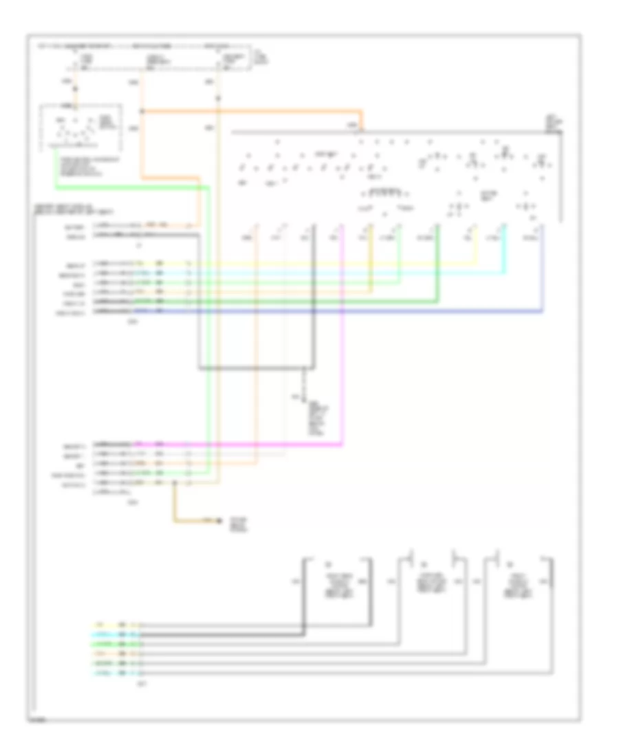
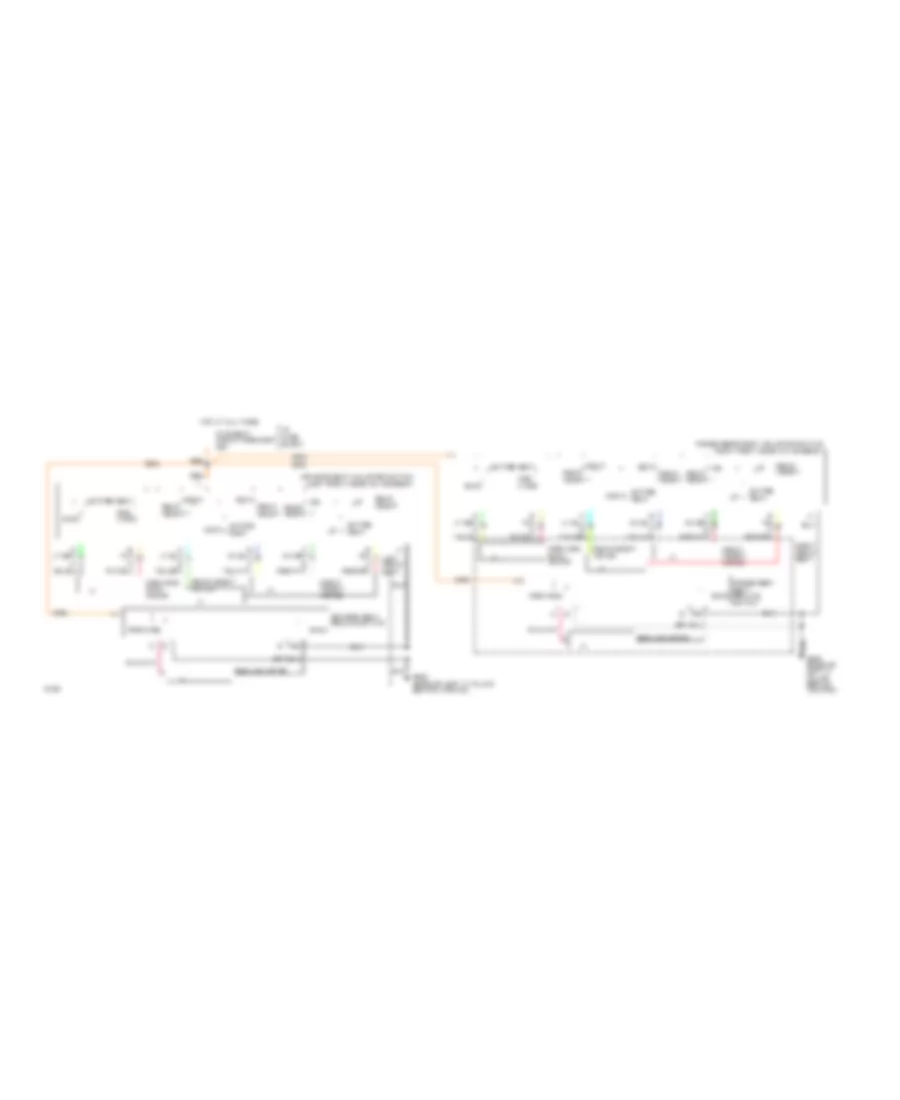
ANTI-LOCK BRAKES Anti-lock Brake Wiring Diagrams (1 of 2) for Cadillac Fleetwood 1994 List of elements for Anti-lock Brake Wiring Diagrams (1 of 2) for Cadillac Fleetwood 1994: 62 (throttle body) 5v reference Abs ind control Adjuster assembly (left top of engine) Adjuster assembly return Battery feed Brake fluid level Btsi/stoplamp switch C11 Data link connector (dlc) (attached to i/p panel carrier, right of steering column) Ebtcm fuse 25a Ebtcm/tps fuse 10a Electronic brake& traction control module (ebtcm) (behind left side of instrument panel, above convenience center) Engine rpm input Fuse block: i/p G200 (base of left 'a' pillar, behind kickpad) Ground Hot at all times Hot in run, bulb test or start Ignition input Ignition power Left front solenoid Left front wheel sensor Left front wheel speed sensor Left rear solenoid Left rear wheel sensor Left rear wheel speed sensor Nca Pilot solenoid control Pnk Powertrain control module (pcm) (left side of engine compartment under air cleaner) Pump on input Pump relay control Red Reference ground Relay feed Right front solenoid Right front wheel sensor Right front wheel speed sensor Right rear solenoid Right rear wheel sensor Right rear wheel speed sensor Serial data link Shield Signal ground Sol monitor input Sol relay control Stop lts fuse 20a Stoplamp switch Tan Throttle position (tp) sensor Throttle position (tp) sensor module (right rear of engine compartment) Throttle position input Tp sensor sig ground Tp sensor voltage Tp sensor vref Trac engaged indicator control Traction engaged signal input Traction indicator control Voltage reference Voltage sense Voltage signal Anti-lock Brake Wiring Diagrams (2 of 2) for Cadillac Fleetwood 1994 List of elements for Anti-lock Brake Wiring Diagrams (2 of 2) for Cadillac Fleetwood 1994: 52 #5 fuse 50a 'brake warning' indicator (red) (behind left headlamp, on radiator support) (left side of engine (right front of engine, taped in engine harness) 87a Base Bpmv pump motor relay Bpmv relay Brake cut-out #1 Brake pressure modulator Brake pressure switch (mounted on master cylinder) Ccm ign 3 fuse 10a Compartment, left of generator) Cruise control module (fastened to left front wheelhousing) Cruise control release switch Cruise on/off signal Cruise switch Electronic traction control switch Fuse block: i/p G106 G110 (front of left cylinder head) G203 (base of right 'a' pillar, behind kickpad) Hot at all times Hot in run Hot in run, bulb test or start I/p indic fuse 10a Ignition coil Ignition signal Instrument cluster Isolation diode Left front valve solenoid Left rear valve solenoid Momen- Multi function lever Nca Off Pilot valve solenoid Pnk R/a Red Return pump motor Right front valve solenoid Right rear valve solenoid Tachometer filter Tan Tan/ Tary Torque converter/ cruise control release switch assembly Underhood electrical center Valve (bpmv) W/ v4f/ v4u limo
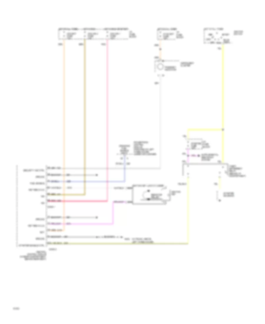
ANTI-THEFT Pass-Key Wiring Diagram for Cadillac Fleetwood 1994 List of elements for Pass-Key Wiring Diagram for Cadillac Fleetwood 1994: 43 "passkey" indicator (behind i/p compartment) (in trunk, above Acc Bat Bulb test Ccm bat fuse 10a Ccm ign 1 fuse 10a Ccm ign 3 fuse 10a Central control module (in rear compartment, behind rear seat) Conn 1 Conn 2 Cranking fuel enable input D13 Fuel enable G402 Ground Hot at all times Hot in run Hot in run or start Hvac bat fuse 10a I/p fuse block Ign Ignition key Ignition key lock cylinder nca Ignition switch Instrument cluster Key res in (hi) Key res in (lo) Left wheelhouse) Lock Nca Off Pnk Powertrain control module (forward of left wheelhouse, under air cleaner) Resistor pellet Run Security ind ctrl Start Starter enable ctrl Starter fuse 10a Starter solenoid Theft deterrent relay
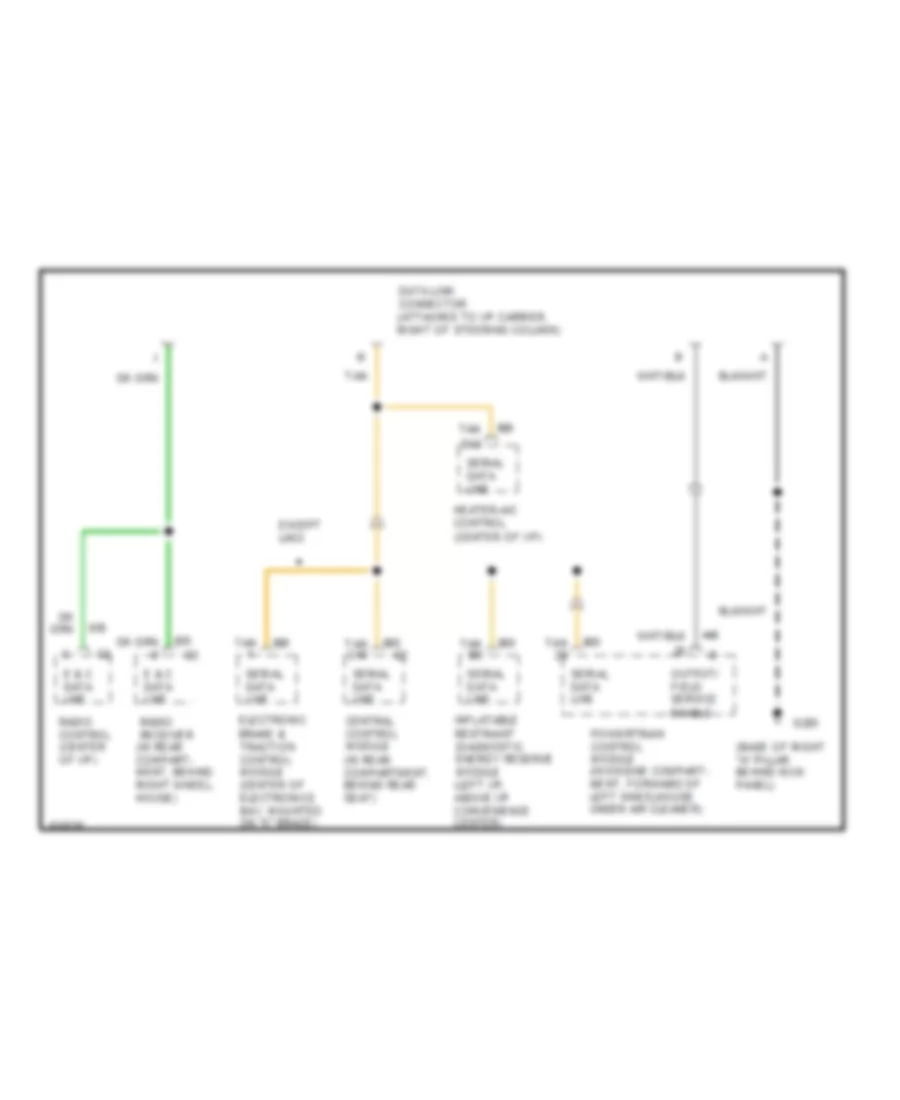
COMPUTER DATA LINES Data Link Connector Wiring Diagram for Cadillac Fleetwood 1994 List of elements for Data Link Connector Wiring Diagram for Cadillac Fleetwood 1994: 18 (base of right "a" pillar behind kick panel) Central control module (in rear compartment, behind rear seat) Data link connector (attached to i/p carrier, right of steering column) E & c data line Electronic brake & traction control module (center of electronics bay, mounted on "x" brace) Except limo G203 Heater-a/c control (center of i/p) Inflatable restraint diagnostic energy reserve module (left i/p, above i/p convenience center) Output/ field service enable Powertrain control module (in engine compart- ment, forward of left wheelhouse under air cleaner) Radio control (center of i/p) Radio receiver (in rear compart- ment, behind right wheel- house) Serial data line Tan Tan b3 Tan c15 Tan d12
CRUISE CONTROL
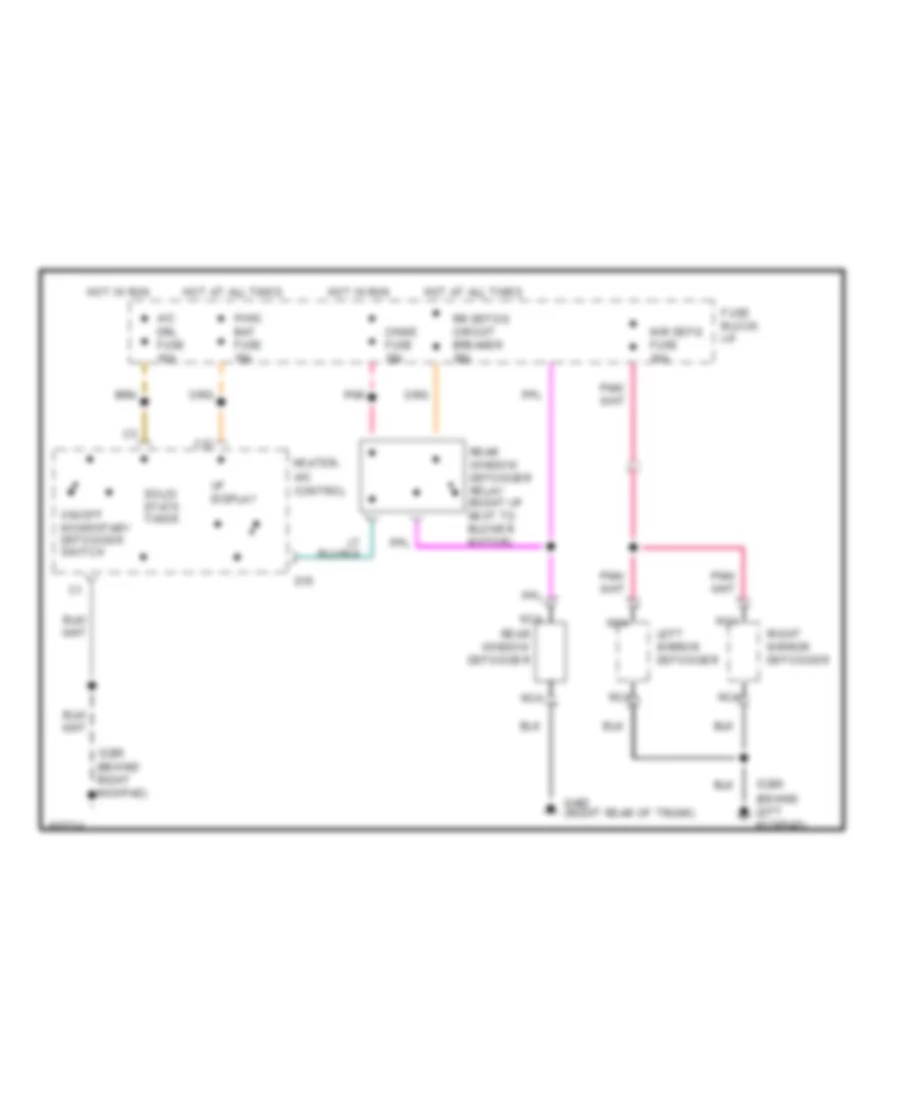
DEFOGGERS Defogger Wiring Diagram for Cadillac Fleetwood 1994 List of elements for Defogger Wiring Diagram for Cadillac Fleetwood 1994: 23 A/c drl fuse 10a C12 Chime fuse 10a D15 Fuse block: i/p G200 (behind left kickpad) G203 (behind right kickpad) G402 (right rear of trunk) Heater- a/c control Hot at all times Hot in run Hvac bat fuse 10a Left mirror defogger Mir defg fuse 10a Nca On/off momentary defogger switch Pnk Rear window defogger Rear window defogger relay (right i/p next to blower motor) Right mirror defogger Rr defog circuit breaker 30a Solid state timer Vf display
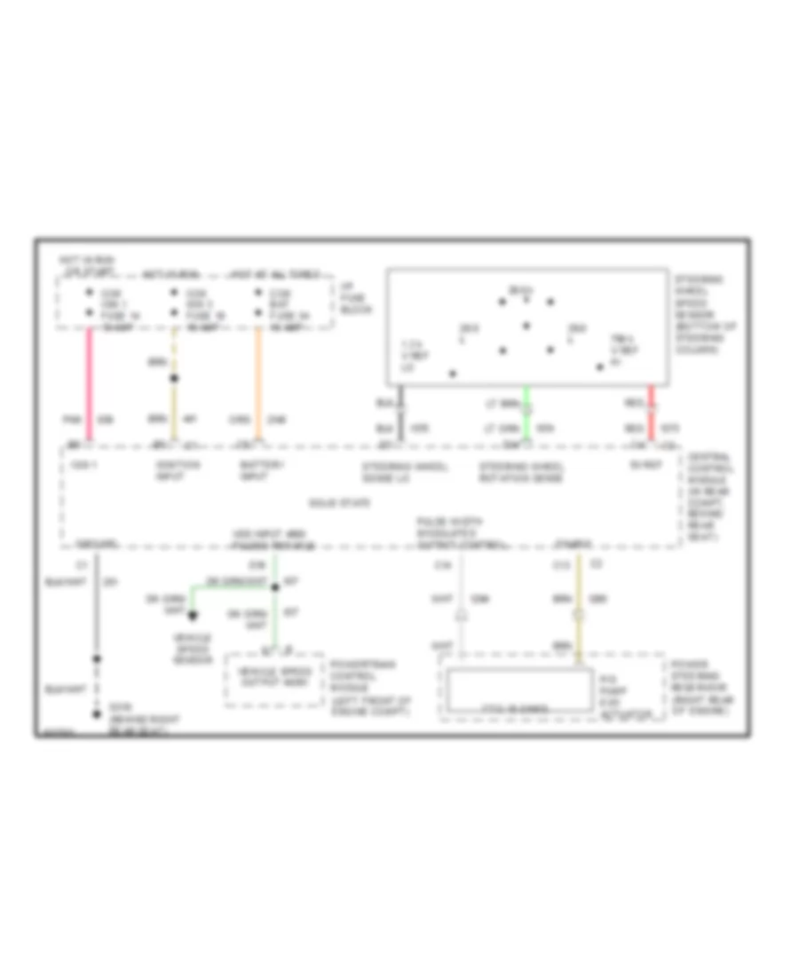
ELECTRONIC POWER STEERING Electronic Power Steering Wiring Diagram for Cadillac Fleetwood 1994 List of elements for Electronic Power Steering Wiring Diagram for Cadillac Fleetwood 1994: 36 1.3 k v ref lo 29.6 k 5v ref 7 to 15 ohms 790 k v ref hi Battery input C13 C14 Ccm bat fuse 34 10 amp Ccm ign 1 fuse 14 10 amp Ccm ign 3 fuse 18 10 amp Central control module (in rear compt, behind rear seat) D14 D16 Enable G310 (behind right rear seat) Ground Hot at all times Hot in run Hot in run or start I/p fuse block Ign 1 Ignition input P/s pump evo actuator Pnk Power steering reservoir (right rear of engine) Powertrain control module (left front of engine compt) Pulse width modulated output control Red Solid state Steering wheel rotation sense Steering wheel sense lo Steering wheel speed sensor (bottom of steering column) Vehicle speed output 4k/mi Vehicle speed sensor Vss input 4000 pulses per mile
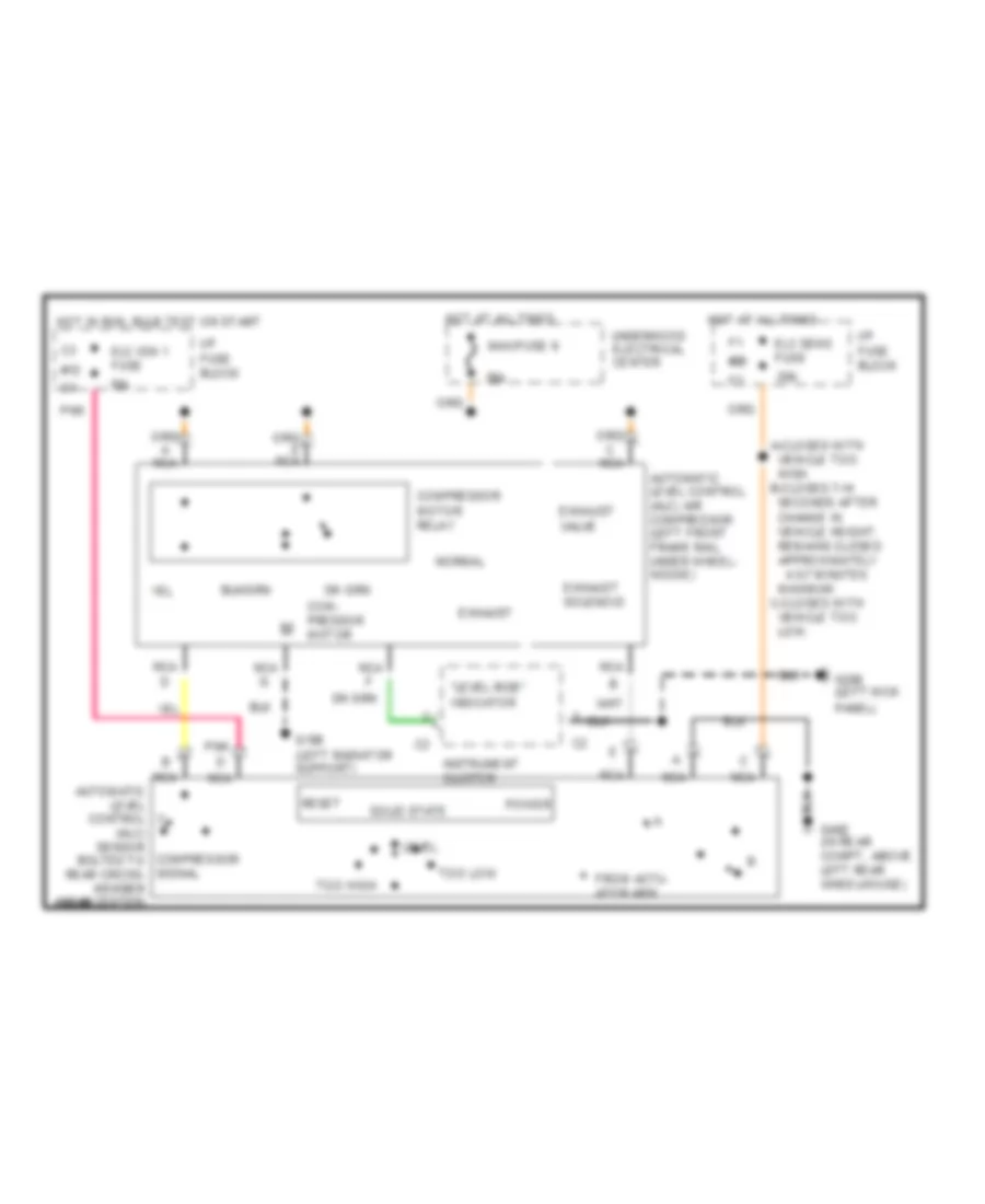
ELECTRONIC SUSPENSION Electronic Level Control for Cadillac Fleetwood 1994 List of elements for Electronic Level Control for Cadillac Fleetwood 1994: 37 maximum. c-closes with vehicle too low. "level ride" indicator #12 #26 10a 20a 30a 4.5-7 minutes A-closes with vehicle too high. b-closes 7-14 seconds after change in vehicle height. remains closed approximately Automatic level control (alc) air compressor (left front frame rail under wheel- house) Com- pressor motor Compressor motor relay Elc ign 1 fuse Elc sens fuse Exhaust Exhaust solenoid Exhaust valve From actu- ator arm G108 (left radiator support) G200 (left kick panel) G402 (in rear compt, above left rear wheelhouse) Hot at all times Hot in run, bulb test or start I/p fuse block Instrument cluster Level Maxifuse 9 Nca Nca automatic level control (alc) sensor compressor bolted to signal rear cross- member near center) Normal Pnk Power Reset Solid state Too high Too low Underhood electrical center
ENGINE PERFORMANCE
5.7L 5.7L (VIN P), Engine Performance Wiring Diagrams (1 of 3) for Cadillac Fleetwood 1994 List of elements for 5.7L (VIN P), Engine Performance Wiring Diagrams (1 of 3) for Cadillac Fleetwood 1994: 82 high res (rear of right cylinder, below exhaust manifold) 5 volts ref A/c clutch status A/c compressor relay A/c request sig Air conditioning system Air pump relay ctrl Battery Central control module (in rear compartment, behind rear seat) Coil Conn a Conn b Coolant fan relays Cruise control, speedo, radio, warning alarm & cent ctrl module Dist ignition feed Dist ref low sig Distributor Egr solenoid ctrl Eng oil level sensor sig Engine oil level sensor (left side of engine oil pan) Fuel enable sig Fuel injector #1 Fuel injector #2 Fuel injector #3 Fuel injector #4 Fuel injector #5 Fuel injector #6 Fuel injector #7 Fuel injector #8 Fuel pump relay ctrl G110 G110 (rear of right cylinder, below exhaust manifold) Ground High resolution sig Hot at all times Hot in run or start Hot in run, bulb test or start Ign Ignition Ignition ctrl Inj #1 ctrl Inj #2 ctrl Inj #3 ctrl Inj #4 ctrl Inj #5 ctrl Inj #6 ctrl Inj #7 ctrl Inj #8 ctrl Inj 1 fuse 10a Inj 2 fuse 10a Instrument clusters system Interface circuit Low oil ind ctrl Low res Low resolution sig Maf sensor sig Mass air flow sensor (between air cleaner and intake resonator) Optical sensor Pcm ground Pcm/fuel pump fuse 15a Pcm/ign fuse 10a Pnk Power steering pressure switch (in power steering line near power unit) Powertrain control module (forward of left wheelhouse, under air cleaner) Pri cool fan relay ctrl Psp switch in Red Ref low Sec cool fan relay ctrl Sensor ground Spark plugs Tcc temp switch (in trans oil cooler inlet pipe) Tcc temp switch sig Trans 1-2 shift ctrl Trans 2-3 shift ctrl Trans 3-2 shift ctrl Under- hood electrical center Vehicle speed sensor (left rear of transmission) Vss ground Vss out Vss signal 5.7L (VIN P), Engine Performance Wiring Diagrams (2 of 3) for Cadillac Fleetwood 1994 List of elements for 5.7L (VIN P), Engine Performance Wiring Diagrams (2 of 3) for Cadillac Fleetwood 1994: 51 (right rear of engine compartment) Air pump fuse 20a Bank 1 h02s low Bank 1 ho2s hi Bank 2 ho2s hi Bank 2 ho2s low Brake switch sig Chime fuse 10a Conn c D pnk Ect sensor sig Egr solenoid valve (top of engine behind inj #7) Emissions fuse 10a Engine coolant temperature sensor (right front of engine) Evaporative emission canister purge solenoid valve (top of engine behind inj #4) G110 (rear of right cylinder, below exhaust manifold) Heated oxygen sensor 1 (bank 1, right exhaust manifold) Heated oxygen sensor 2 (bank 2, left exhaust manifold) Hot at all times Hot in run, bulb test or start Iac coil "a" hi Iac coil "a" low Iac coil "b" hi Iac coil "b" low Iat sensor sig Idle air control motor (right front of throttle body) Instrument cluster system Intake air temperature sensor (air cleaner assembly) Manifold absolute pressure sensor Map sensor sig Nca Pcm ground Pnk Pnp sig Powertrain control module (forward of left wheelhouse, under air cleaner) Red Red a Red b Secondary air injection pump assembly (lower right side of engine block) Secondary air injector (air) pump relay Tan Tcc/cruise/ brake switch (on brake pedal support bracket) Throttle position sensor (attached to throttle body) a Tp sensor interface module (attached to a/c accumulator except limo) Tp sensor sig Traction engaged sig Trans press ctrl sol hi Trans range sig "a" Trans range sig "b" Trans range sig "c" Under- hood electrical center 5.7L (VIN P), Engine Performance Wiring Diagrams (3 of 3) for Cadillac Fleetwood 1994 List of elements for 5.7L (VIN P), Engine Performance Wiring Diagrams (3 of 3) for Cadillac Fleetwood 1994: 64 (rear of right cylinder, below exhaust manifold) 1-2 shift solenoid 2-3 shift solenoid 3-2 ctrl solenoid (pwm) A/c clutch ctrl A/c compressor relay A/c press sensor sig A/c refrigerant pressure sensor (in hi pressure line above right wheelhouse) Automatic transmission Canister purge ctrl Change oil ind ctrl Chime fuse 10a Coil driver Conn d Data link connector (right of steering column) Exterior lights system (backup lights circuit) Forward gear switch Fuel pump priming connector (near a/c accumulator) Fuel pump relay (behind under- hood electrical center) Fuel pump/ level sender (in fuel tank) Fuel pump/ oil pressure switch (lower left side of engine) G110 G110 (rear of right cylinder, below exhaust manifold) G203 (base of right "a" pillar, behind kick panel) G402 (above left rear wheelhouse) Ground Hot at all times Hot in run, bulb test or start I/p indc fuse 10a Ign Ign ctrl Ignition Ignition coil (front of engine) Ignition coil module (front of engine) Instrument cluster Instrument cluster system Isolation diode Knock sensor sig Left knock sensor (bottom left side of engine block) Malfunction indicator Mil ctrl Output/field serv enbl Park/neutral position relay (convenience center) Pcm ground Pcm/fuel pump fuse 15a Pcm/ign fuse 10a Pnk Powertrain control module (forward of left wheelhouse, under air cleaner) Pressure control solenoid Red Right knock sensor (bottom right side of engine block) Serial data Sw a Sw b Sw c Tach- ometer filter Tan Tan m Tcc solenoid Trans fluid temp sensor Trans fluid temp sig Trans press ctrl low Trans tcc ctrl Under- hood electrical center
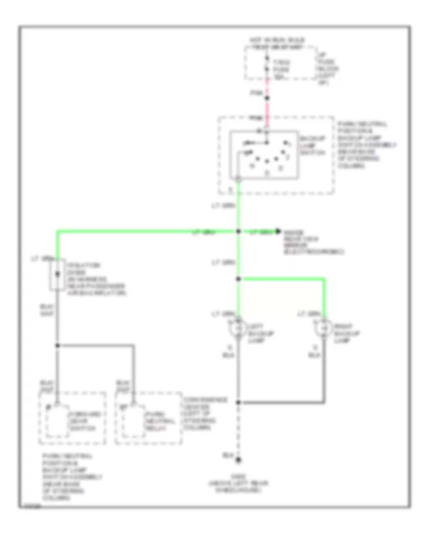
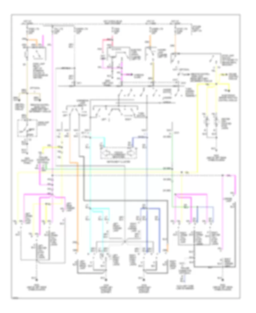
EXTERIOR LIGHTS Back-up Lamps Wiring Diagram for Cadillac Fleetwood 1994 List of elements for Back-up Lamps Wiring Diagram for Cadillac Fleetwood 1994: 14 Backup lamp switch Convenience center (left of steering column) Forward gear switch G402 (above left rear wheelhouse) Hot in run, bulb test or start I/p fuse block (left i/p) Inside rear view mirror (electrochromic) Isolation diode (in harness, near passenger air bag inflator) Left backup lamp Park/ neutral position & backup lamp switch assembly (near base of steering column) Park/ neutral relay Pnk Right backup lamp T/sig fuse 15a Exterior Light Wiring Diagram for Cadillac Fleetwood 1994 List of elements for Exterior Light Wiring Diagram for Cadillac Fleetwood 1994: 66 A right front marker lamp b A10 Auxiliary wire (use as needed) Brake/traction control module C210 C211 Center high mounted stop lamps Central control module Cornering lamp switch Cornr lts fuse 10a Cruise control module Deterrent module Door lock Electric turn signal flasher (left i/p) Electronic G108 (upper left radiator support) G109 (upper right radiator support) G200 (left kick panel) G203 (right kick panel) G402 (above left rear wheelhousing) Hazard Hazard lamp flasher (left i/p) Hazard switch Hazrd lts fuse 20a Head Headlamp switch Hot at all times Hot in run, bulb test or start I/p fuse block (left i/p) Instrument cluster Lamp Left Left center tail/ stop/ turn lamps Left corn- ering lamp Left front marker lamp Left front park/ turn lamps Left upper tail/ stop/ turn lamps License Nca Normal Not used Off Optional Park Park lamp relay (left of steering column, in convenience center) Park lts fuse 20a Pnk Receiver/theft Remote control Remote control door lock receiver/theft deterrent module Right Right corn- ering lamp Right front park/ turn lamps Right rear marker light Right upper tail/ stop lamp Right upper tail/ stop/ turn lamps Stop lamp switch (attached to brake pedal bracket) Stop lts fuse 20a T/sig fuse 15a Tail lts fuse 10a Timer Trailer connector (optional) Turn switch Turn/ hazard- switch assembly Vacuum fluorescent indicators Warning alarm
GROUND DISTRIBUTION
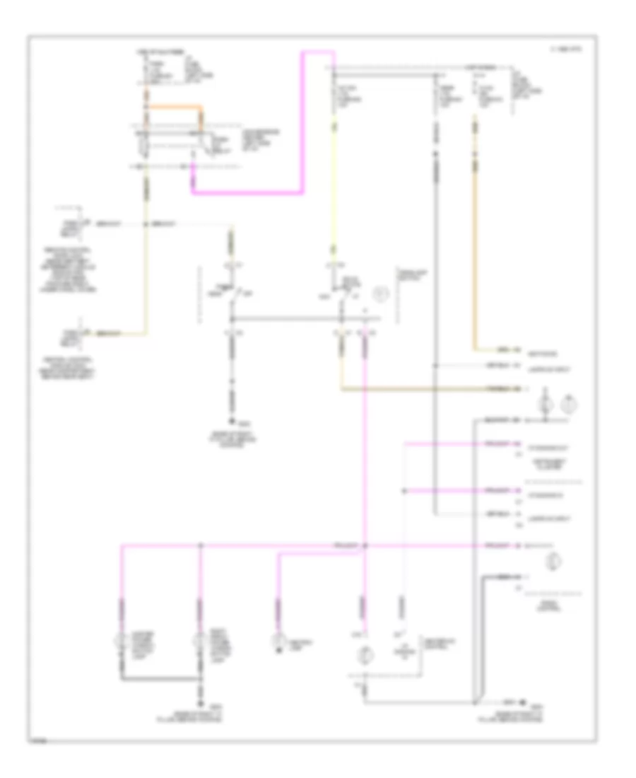
HEADLIGHTS Headlight Wiring Diagram, with DRL for Cadillac Fleetwood 1994 List of elements for Headlight Wiring Diagram, with DRL for Cadillac Fleetwood 1994: 72 #14 #18 10a #34 (behind (center of i/p carrier, (in trunk, behind rear seat) (left side of i/p, left (right 10a A10 A11 Ambient lt sensor Battery input Below defroster grill) Block C16 Cb 20a Ccm bat Ccm ign 1 Ccm ign 3 Central control module (ccm) Cluster Conn c1 Conn c2 Convenience center Delay Delay pot return Dimmer Disable Flash From From maxifuse #11 Fuse G106 G107 G203 Hdlp Headlt Headlt relay Headlt rly Headlt sw Headlts Hi beam Hot Hot at all times Hot in I/p Ignition #1 Ignition #3 In run Ind Instrument Kickpad, base Left Left headlt, on Lo beam Maxifuse #2 Of a pillar) Of steering column) Photoresistor hi Photoresistor lo Pnk Pnk 839 Radiator support) Right Right headlt, on Run or start Tan Tan 270 Twilight Twilight delay pot Twilight disable Headlight Wiring Diagram, without DRL for Cadillac Fleetwood 1994 List of elements for Headlight Wiring Diagram, without DRL for Cadillac Fleetwood 1994: 78 #14 #18 10a #34 (behind (bolted above (center of i/p carrier, (drl) relay (in trunk, behind rear seat) (left side of i/p, left (right 10a A10 A11 Ambient lt sensor Battery input Below defroster grill) Block C16 Cb 20a Ccm bat Ccm ign 1 Ccm ign 3 Central control module (ccm) Cluster Conn c1 Conn c2 Convenience center Daytime Delay Delay pot return Dimmer Diode assembly Disable Drl enable From From maxifuse #11 Fuse G106 G107 G203 Hdlp Headlt Headlt relay Headlt rly Headlt sw Headlts Hi beam Hot Hot at all times Hot in I/p Ignition #1 Ignition #3 In run Ind Instrument Kickpad, base Left Left headlt, on Lo beam Maxifuse #2 Of a pillar) Of steering column) Photoresistor hi Photoresistor lo Pnk Pnk 839 Radiator support) Right Right headlt, on Run or start Running lts Steering column) Tan Tan 270 Twilight Twilight delay pot Twilight disable
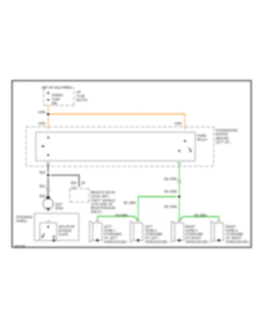
HORN Horn Wiring Diagram for Cadillac Fleetwood 1994 List of elements for Horn Wiring Diagram for Cadillac Fleetwood 1994: 13 Convenience center (behind left i/p) Horn relay Horns fuse 25a Hot at all times I/p fuse block Inflator module plate Left horn 1 (forward of left wheelhouse) Left horn 2 (forward of left wheelhouse) Remote door lock/ anti- theft module (top side of rear package shelf) Right horn 3 (forward of right wheelhouse) Right horn 4 (forward of right wheelhouse) Slip ring Steering wheel
INSTRUMENT CLUSTER
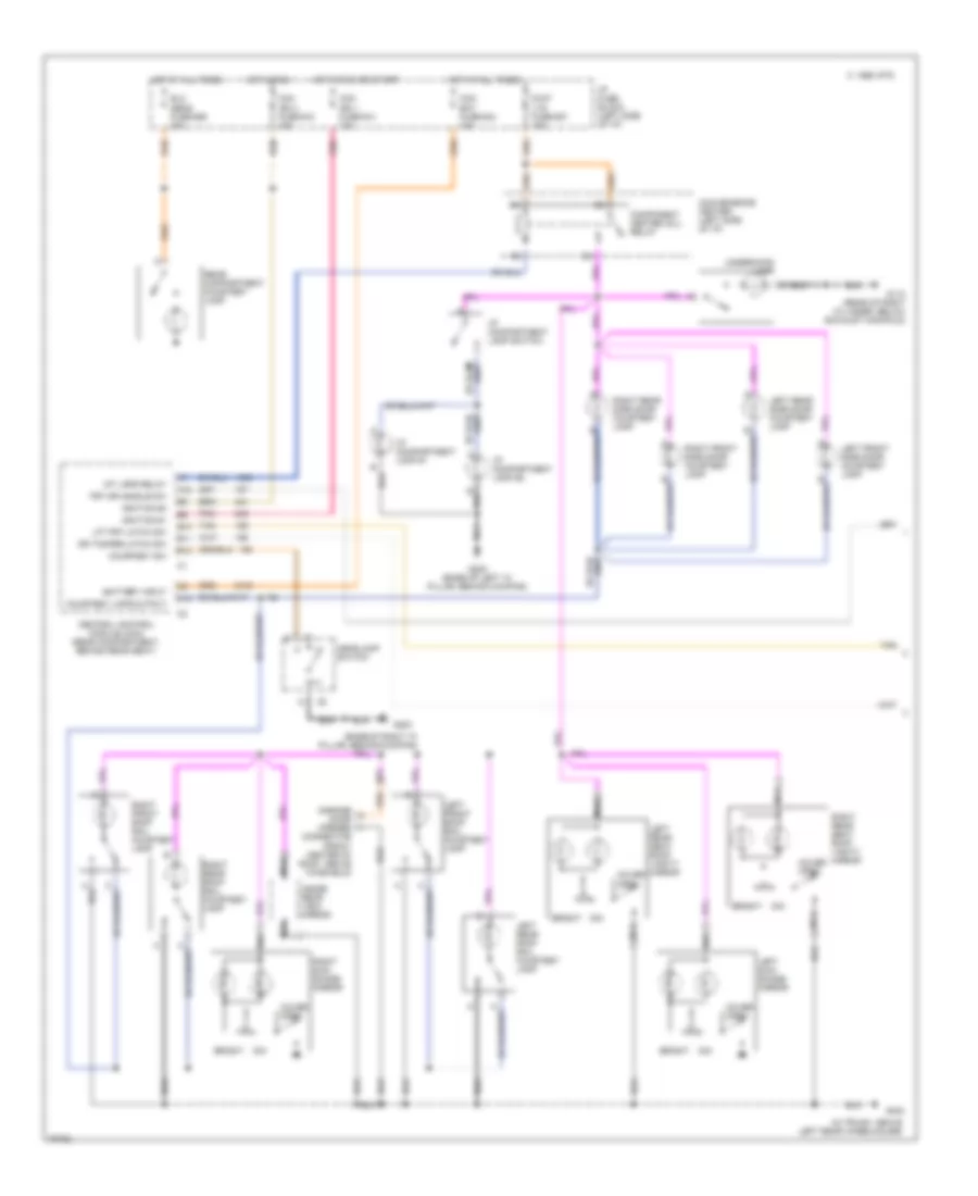
INTERIOR LIGHTS Courtesy Lamps Wiring Diagram (1 of 2) for Cadillac Fleetwood 1994 List of elements for Courtesy Lamps Wiring Diagram (1 of 2) for Cadillac Fleetwood 1994: 60 (base of right "a" pillar, behind kickpad) (in trunk, above left rear wheelhouse) A12 B10 B11 B12 Battery input Bright C 1995 vftc C12 Ccm bat fuse #34 10a Ccm ign 1 fuse #14 10a Ccm ign 3 fuse #18 10a Central control module (ccm) (rear compartment, behind rear seat) Component center (dil) relay Connector (front center of roof, above winshield) Convenience center (left side of i/p) Courtesy lmps output Courtesy sw Cover open D/int lts fuse #27 15a Dim Dr tamper latch sw Elc sens fuse #26 20a Frt dr handle sw G110 (rear of right cylinder, below exhaust manifold) G200 (base of left "a" pillar, behind kickpad) G203 G402 Garage door opener Headlamp switch Hot at all times Hot in run Hot in run or start I/p compartment lamp #1 I/p compartment lamp #2 I/p compartment lamp switch I/p fuse block (left side of i/p) Ignition #1 Ignition #3 Inside rear view mirror Int lmps relay Left front roof rail courtesy lamp Left front side door courtesy lamp Left rear roof rail courtesy lamp Left rear seat roof vanity mirror Left rear side door courtesy lamp Left sun- shade mirror Lft frt latch sw Nca Pnk Rear compartment courtesy lamp Right front roof rail courtesy lamp Right front side door courtesy lamp Right rear roof rail courtesy lamp Right rear seat roof vanity mirror Right rear side door courtesy lamp Right sun- shade mirror Tan Underhood lamp Courtesy Lamps Wiring Diagram (2 of 2) for Cadillac Fleetwood 1994 List of elements for Courtesy Lamps Wiring Diagram (2 of 2) for Cadillac Fleetwood 1994: 19 base base others (in trunk, above left rear wheelhouse) Base Door latch/ tamper G402 Ignition key alarm switch Illuminated entry Left front mini wedge door lock assembly Left rear mini wedge door lock assembly Nca Others Remote control door lock receiver theft deterrent module (rcdlr/tdm) Right front mini wedge door lock assembly Right front theft deterrent door lock (tamper) switch Right rear mini wedge door lock assembly Switch Tan Instrument Illumination Wiring Diagram for Cadillac Fleetwood 1994 List of elements for Instrument Illumination Wiring Diagram for Cadillac Fleetwood 1994: 34 (base of right "a" pillar, behind kickpad) A2 Ashtray lamp C 1995 vftc C16 C6 Central control module (ccm) (rear compartment, behind rear seat) Convenience center (left side of i/p) Crnr lts fuse #41 10a G203 Head Headlamp switch Heater-a/c control Hot at all times Hot in run Hvac ign fuse #12 10a I/p fuse block (left side of i/p) Ignition #3 Instrument cluster Int dim lts fuse #42 10a Lamps on input Master power window switch lamp Max Off Park Park lamps relay Park lp relay Park lts fuse #31 20a Radio control Remote control door lock receiver/theft deterrent module (rcdlr/tdm) (top of rear package shelf, under chmsl cover) Right front power window switch lamp Solid state Vf dimming in Vf dimming out
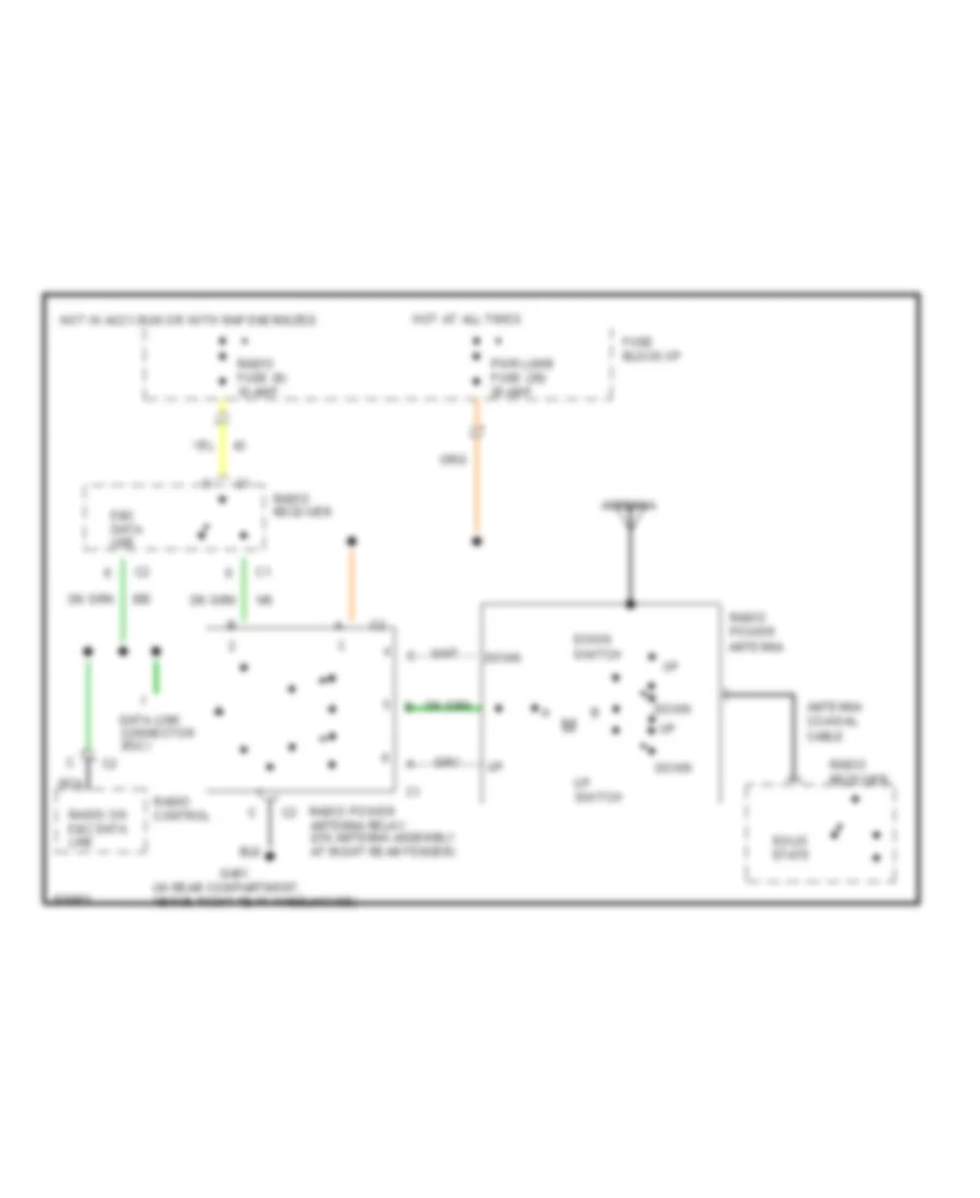
POWER ANTENNA Power Antenna Wiring Diagram for Cadillac Fleetwood 1994 List of elements for Power Antenna Wiring Diagram for Cadillac Fleetwood 1994: 22 (in rear compartment, above right rear wheelhouse) Antenna Antenna coaxial cable Data link connector (dlc) Down Down switch Down up E&c data line Fuse block:i/p G401 Hot at all times Hot in accy,run or with rap energized Nca Pwr lumb fuse (39) 20 amp Radio control Radio fuse (9) 10 amp Radio on e&c data line Radio power antenna Radio power antenna relay (on antenna assembly at right rear fender) Radio receiver Solid state Up switch
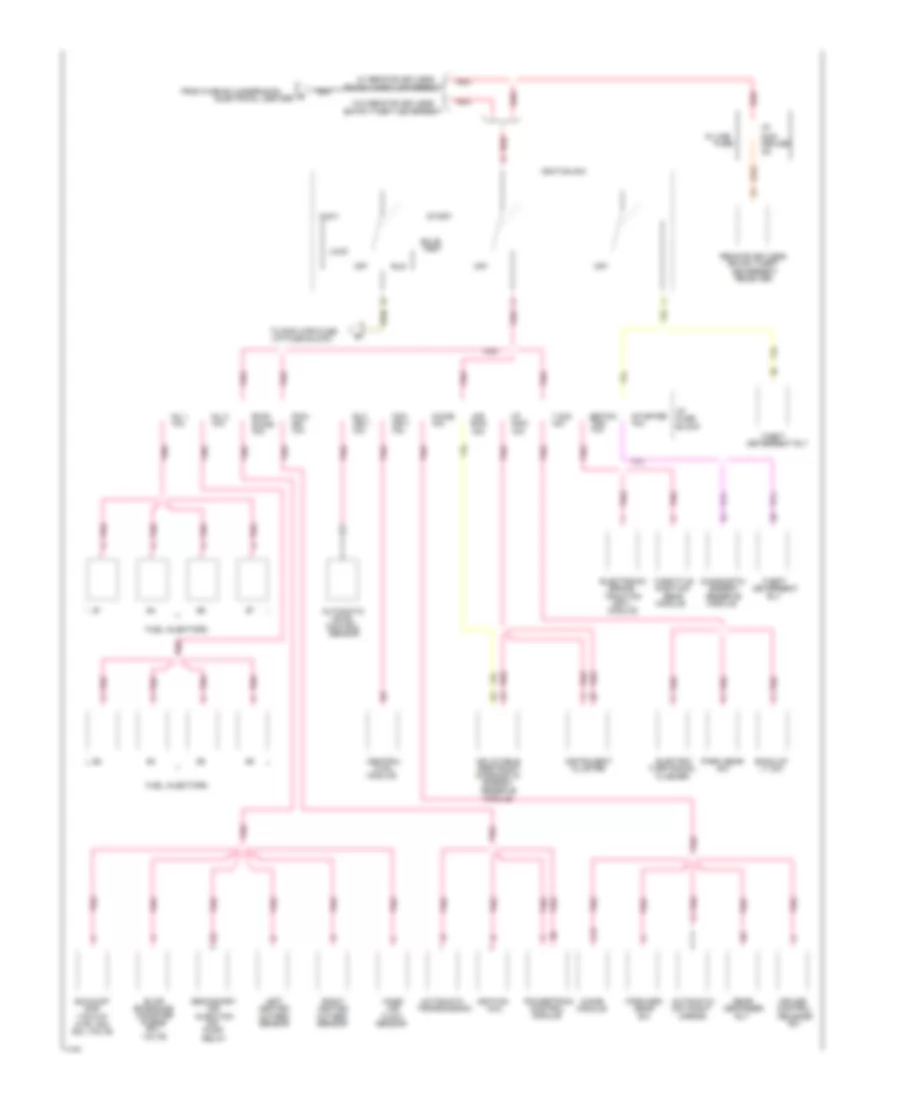
POWER DISTRIBUTION
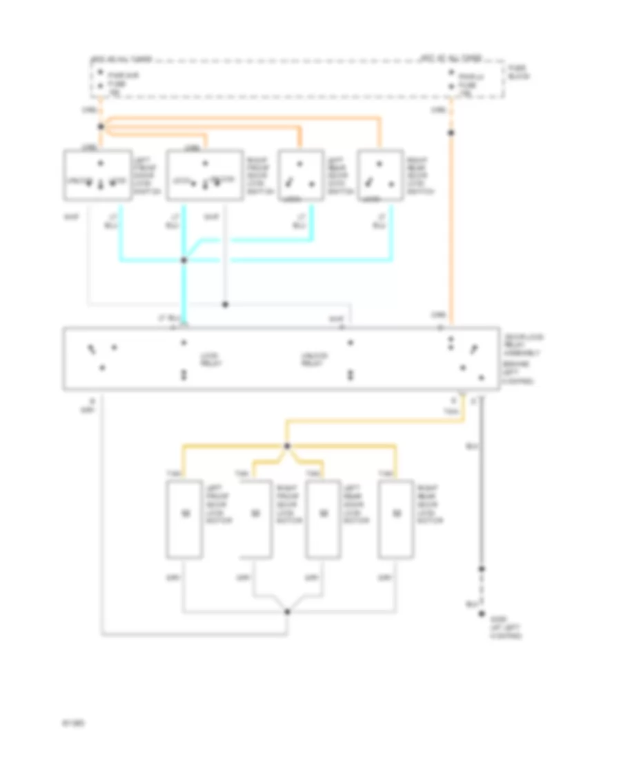
POWER DOOR LOCKS Power Door Lock Wiring Diagram, with Remote/Keyless Entry for Cadillac Fleetwood 1994 List of elements for Power Door Lock Wiring Diagram, with Remote/Keyless Entry for Cadillac Fleetwood 1994: 80 "a" pillar behind (base of left (base of left "a" pillar, behind kick panel) (behind left rear wheelhouse) program connector (on base of steering column) (on brake pedal bracket) 10a 20a A12 And backup lamp switch B11 Battery Brake input C10 C11 C12 door latch tamper input C13 C14 C15 C16 Ccm ign3 fuse Central control module (in trunk behind rear seat) Concealed fuse Convenience center D10 D11 D12 D13 D14 D15 D16 Disarm input Door lock relay Fuel tank filler door lock actuator Fuse G200 G402 (in trunk, above rear wheelhouse) Ground Headlight relay Horn control Horns system Hot at all times Hot in run I/p concealed I/p fuse block Ignition Illuminated entry Instrument cluster system Kick panel) Left front door lock actuator Left front door lock switch Left key disarm switch Left rear door lock actuator Left rear door lock switch Lock Lock output Lock relay Park gear switch Park input Park light relay Park lp relay Park/neutral position Program connect input Pwr lk fuse Pwr mir fuse Rear compartment lid lock release actuator Rear compartment lid release Rear compartment lid release switch Remote control door lock receiver and theft deterrent module (mounted on rear package shelf under chmsl cover) Right front door lock actuator Right front door lock switch Right key disarm switch Right rear door lock actuator Right rear door lock switch Security system indicator Stop lamp switch Tan Unlock Unlock output Unlock relay Power Door Lock Wiring Diagram, without Remote/Keyless Entry for Cadillac Fleetwood 1994 List of elements for Power Door Lock Wiring Diagram, without Remote/Keyless Entry for Cadillac Fleetwood 1994: 22 (behind left kickpad) Assembly Door lock Fuse block G200 (at left kickpad) Hot at all times Left front door lock motor Left front door lock switch Left rear door lock motor Left rear door lock switch Lock Lock relay Pwr lk fuse 10a Pwr mir fuse 10a Relay Right front door lock motor Right rear door lock motor Right front door lock switch Right rear door lock switch Tan Unlock Unlock relay
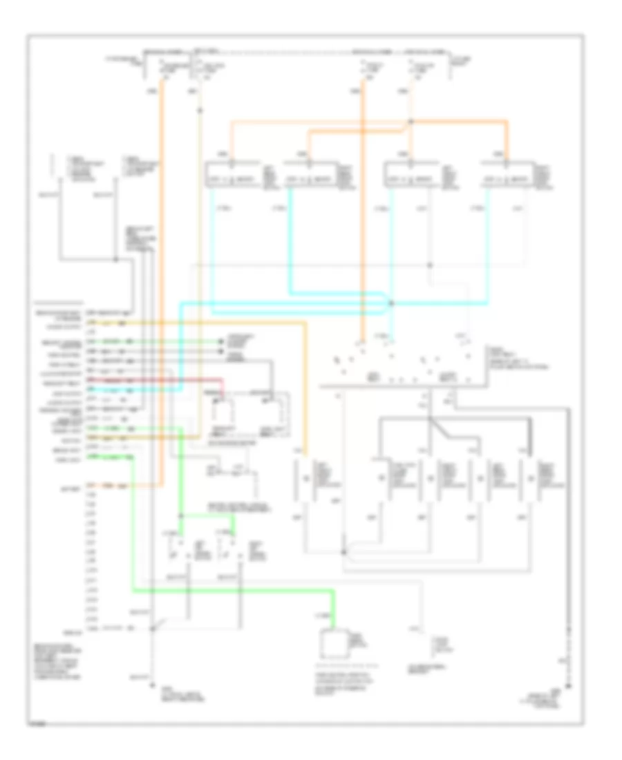
POWER MIRRORS Power Mirror Wiring Diagram for Cadillac Fleetwood 1994 List of elements for Power Mirror Wiring Diagram for Cadillac Fleetwood 1994: 39 m (base of left "a" pillar, behind kickpad) (in trunk, above left rear wheelhouse) Ambient light sensor (winshield side) Automatic day/night mirror Backup lamp switch Chime fuse 10a Down G200 G402 Ground Headlamp sensor (mirror side) Hot at all times Hot in run, bulb test or start I/p fuse block Indicator control Inside rearview mirror (electro-chromic) Left Left outside rearview mirror Left/right motor Mirror "on" Mirror position switch Mirror select switch Mirror switch Nca Off On indicator Outside remote control rearview mirror switch Park/neutral and backup switch assembly Pnk Pwr mir fuse 10a Reset to daytime high reflectivity in reverse Right Right outside rearview mirror Solid state T/sig fuse 15a Up/down motor
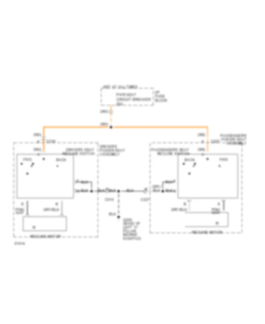
POWER SEATS Heater Wiring Diagram for Cadillac Fleetwood 1994 List of elements for Heater Wiring Diagram for Cadillac Fleetwood 1994: 46 g200 (base of left "a" pillar behind kickpad) (base of left a" pillar, behind kickpad) 5.9 k B red Back cushion Back element Bat C316 C321 C322 C323 C324 C325 C327 C328 C329 C330 C331 C332 Driver's heated seat switch Driver's seat G200 Ground Heated seat module Heater Heater ground Hot at all times Hot in run Htd seat fuse 15a I/p fuse block Ign Mem seat fuse 10a Nca Ntc 1 Ntc 2 Ntc sensor Off Passenger heated seat switch Passenger's seat Red Seat cushion Seat element Seat heater "on" led Temp select in Temp select out Lumbar Wiring Diagram for Cadillac Fleetwood 1994 List of elements for Lumbar Wiring Diagram for Cadillac Fleetwood 1994: 37 10a 20a Deflate Deflate relay Driver seat Driver seat back lumbar support switches Driver seat lumbar/ recliner switch assembly (bottom outboard side of left front seat) Driver seat pneumatic control manifold (below left front seat) G200 (left kick panel) Hot at all times I/p fuse block Inflate Inflate relay Lower Lower lumbar bladder Lower lumbar blader Lower lumbar solenoid valve Middle Middle lumbar bladder Middle lumbar blader Middle lumbar solenoid valve Passenger power seat assembly Passenger seat Passenger seat back lumbar support switches Passenger seat lumbar/recliner switch assembly (bottom outboard side of right front seat) Passenger seat pneumatic control manifold (below right front seat) Power seat pneumatic control module (below right front seat) Pressure vacuum Pump assembly (below right front seat) Pump cutoff relay (solid state) Pwr lumb fuse Pwr mir fuse Sensor switch Upper Upper lumbar bladder Upper lumbar blader Upper lumbar solenoid valve Memory Seat Wiring Diagram for Cadillac Fleetwood 1994 List of elements for Memory Seat Wiring Diagram for Cadillac Fleetwood 1994: 46 15a 25a Back Battery C317 C318 C319 Circuit breaker 3 Easy exit Entire seat Forward Forward/ back motor (below left front seat) Front down Front up Front up/down motor (below left front seat) Frt dn Frt up Fwd G200 (base of left "a" pillar behind kick oanel) Ground Hot at all times Hot in run Hot in run, bulb test or start I/p fuse block Ignition 3 Left power seat switch Mem 1 Mem 2 Mem/seat fuse Memory 1 Memory 2 Memory seat module (below center of left seat) Nca Nca nca Park gear switch Park position Park/neutral and backup lamp switch (on bottom of steering column) Power seats system Rear down Rear up Right rear up/down motor (below left front seat) Rr dn Rr up Set T/sig fuse Tan Power Seat Wiring Diagram for Cadillac Fleetwood 1994 List of elements for Power Seat Wiring Diagram for Cadillac Fleetwood 1994: 22 Back Down Driver's seat adjuster switch (left front door, on armrest) Driver's seat recline switch E tan Entire seat For- ward Forward Forward/ back motor Front height Front height motor G200 (base of left "a" pillar behind kickpad) Hot at all times I/p fuse block Left front seat Passenger seat recline switch Passenger's seat adjuster switch right front door, on armrest) Pwr seat circuit breaker 25a Rear height Rear height motor Recline motor Right front seat Recliner Wiring Diagram, with Memory Seats for Cadillac Fleetwood 1994 List of elements for Recliner Wiring Diagram, with Memory Seats for Cadillac Fleetwood 1994: 13 Back C316 C327 Driver's power seat assembly Driver's seat recline switch Fwd G200 (base of left "a" pillar, behind kickpad) Hot at all times I/p fuse block Passenger's power seat assembly Passenger's seat recline switch Pwr seat circuit breaker 25a Recline motor
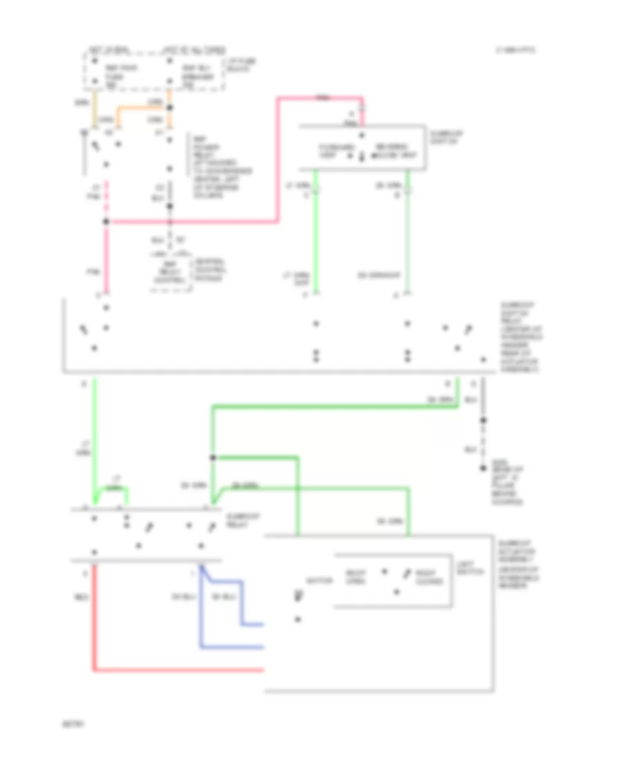
POWER TOP/SUNROOF Power Top/Sunroof Wiring Diagrams for Cadillac Fleetwood 1994 List of elements for Power Top/Sunroof Wiring Diagrams for Cadillac Fleetwood 1994: 24 (center of windshield header) C 1994 vftc C1 pnk Central control module Forward/ vent G200 (base of left "a" pillar, behind kickpad) Hot at all times Hot in run I/p fuse block Limit switch Motor Pnk Rap power relay (attaqched to convenience center, left of steering column) Rap pwr fuse 30a Rap relay control Rap rly breaker 30a Red Reverse/ close vent Roof closed Roof open Sunroof actuator assembly Sunroof relay Sunroof switch Sunroof switch relay (center of windshield header, rear of actuator assembly)
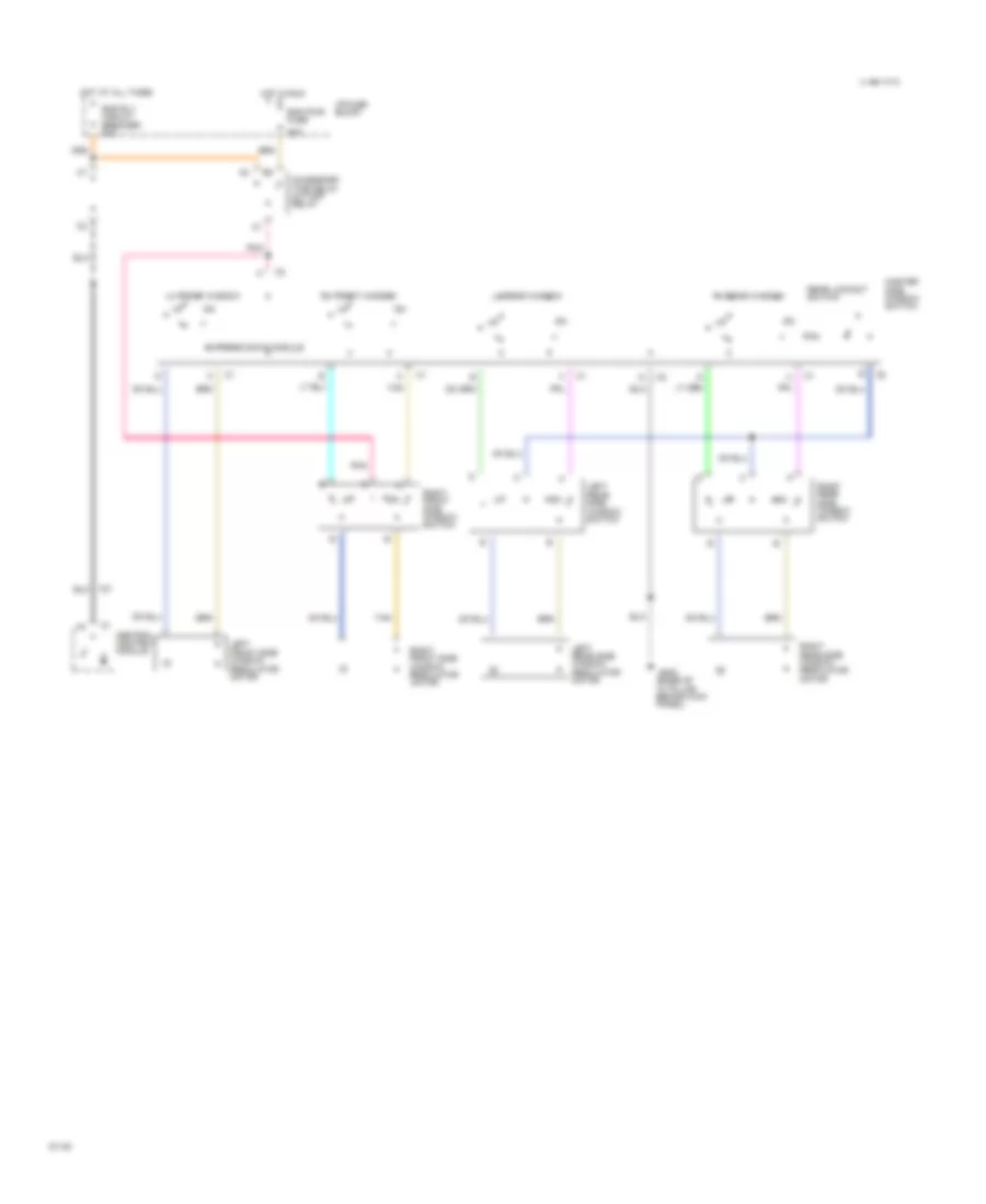
POWER WINDOWS Power Window Wiring Diagram for Cadillac Fleetwood 1994 List of elements for Power Window Wiring Diagram for Cadillac Fleetwood 1994: 26 30a Accessory time delay cut-off relay C 1994 vftc Central control module Express down module G200 (base of "a" pillar behind kick panel) Hot at all times Hot in run I/p fuse block Left front side window regulator motor Left rear side window regulator motor Left rear side window switch Lh front window Lh rear window Master side window switch Pnk Rap pwr fuse Rap rly circuit breaker 30a Rear lockout switch Rh front window Rh rear window Right front side window regulator motor Right front side window switch Right rear side window regulator motor Right rear side window switch Tan
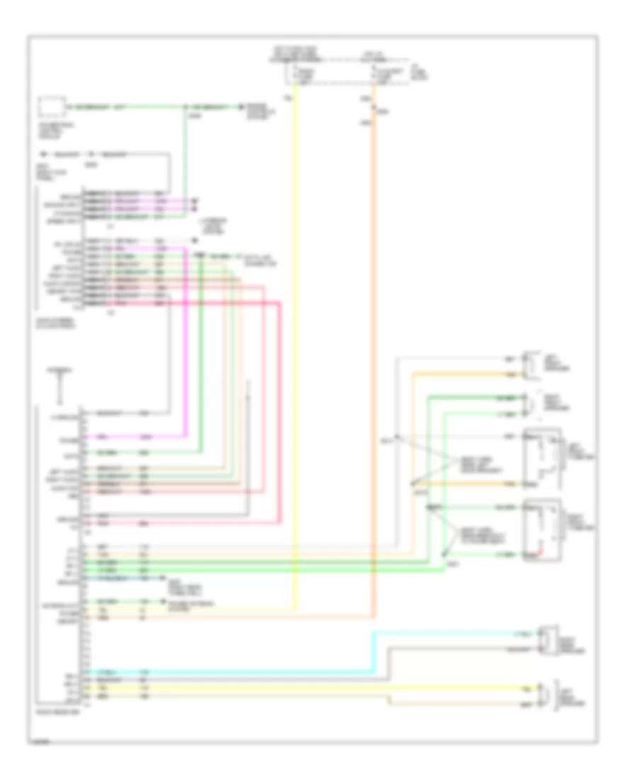
RADIO Radio Wiring Diagrams for Cadillac Fleetwood 1994 List of elements for Radio Wiring Diagrams for Cadillac Fleetwood 1994: 60 (body harn, near breakout to power seat) (body harn, near left door grommet) 14v Am/fm stereo & clock radio Antenna Antenna out Audio com Audio common Data Data link connector Dimming input Engine controls system G203 (right kick panel) G403 (right rear wheelwell) Ground Hi ground Hot at all times Hot in acc, run or w/ retained accessory power Hvac/bat fuse 10a I/p fuse block Interior lights system Left audio Left front speaker Left front tweeter Left rear speaker Lf (+) Lf (-) Lr (+) Lr (-) Mem Memory Memory pwr Nca Pk lps on Pnk Power Power antenna system Powertrain control module Radio fuse 10a Radio receiver Red Rf (+) Rf (-) Right audio Right front speaker Right front tweeter Right rear speaker Rr (+) Rr (-) S206 S210 S246 S254 S314 S315 S320 S321 Speed input Tan Vf dimming
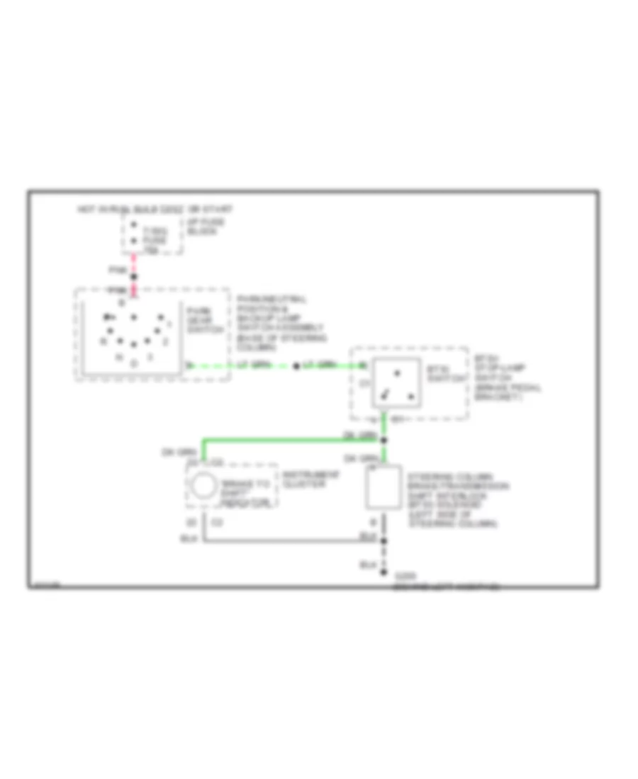
SHIFT INTERLOCKS Shift Interlock Wiring Diagram for Cadillac Fleetwood 1994 List of elements for Shift Interlock Wiring Diagram for Cadillac Fleetwood 1994: 12 "brake to shift" indicator Btsi switch Btsi/ stop-lamp switch (brake pedal bracket) G200 (behind left kickpad) Hot in run, bulb test or start I/p fuse block Instrument cluster Park gear switch Park/neutral position & backup lamp switch assembly (base of steering column) Pnk Steering column brake/transmission shift interlock (btsi) solenoid (left side of steering column) T/sig fuse 15a
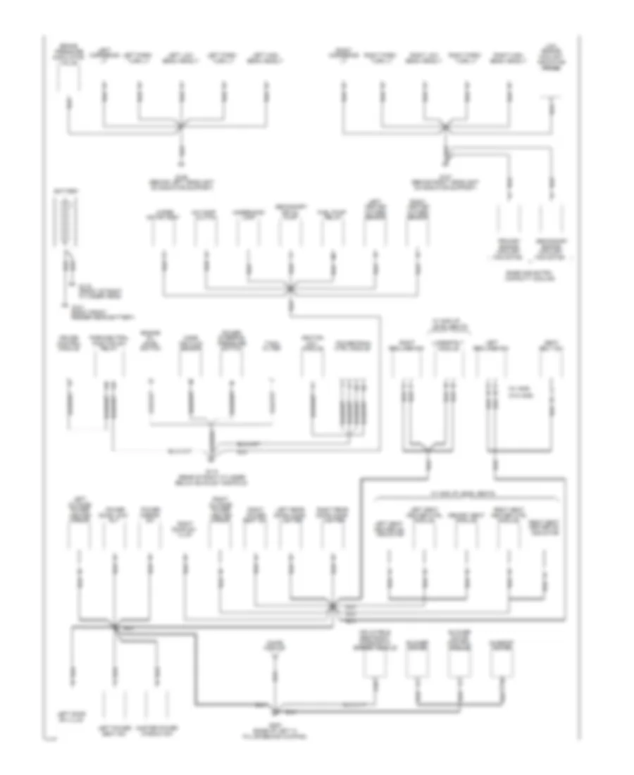
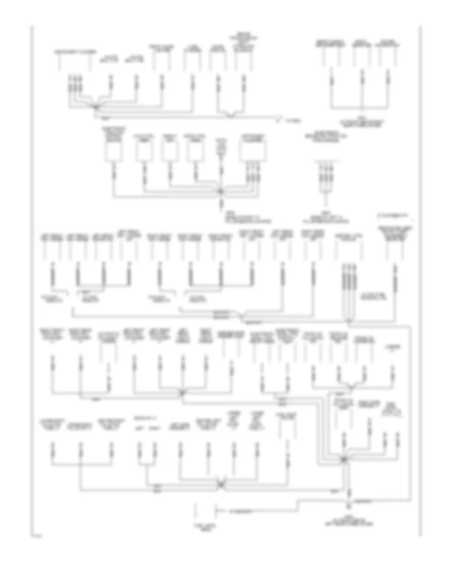
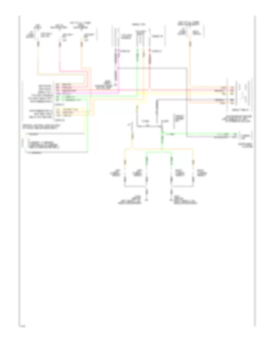
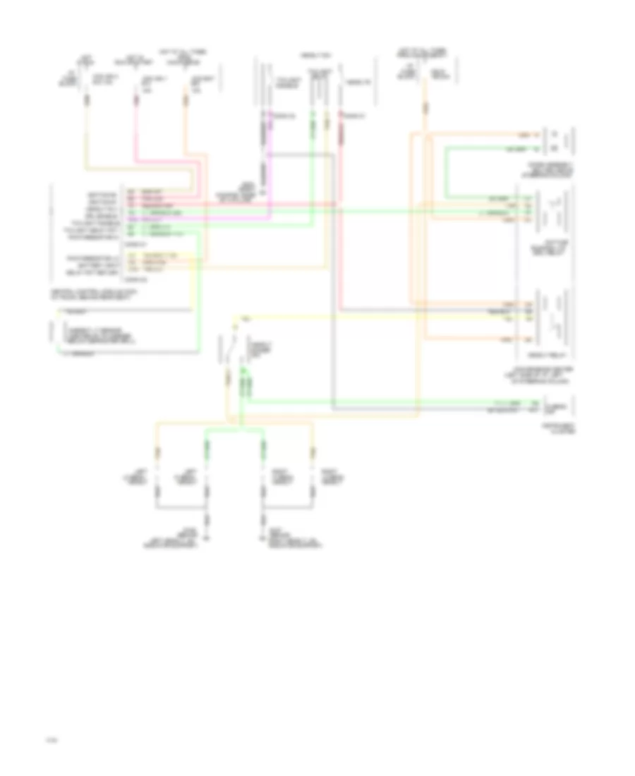
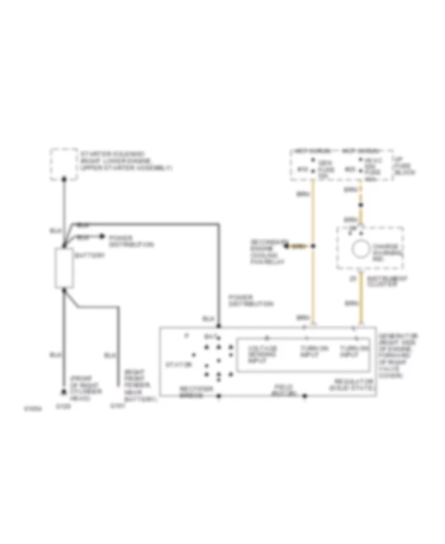
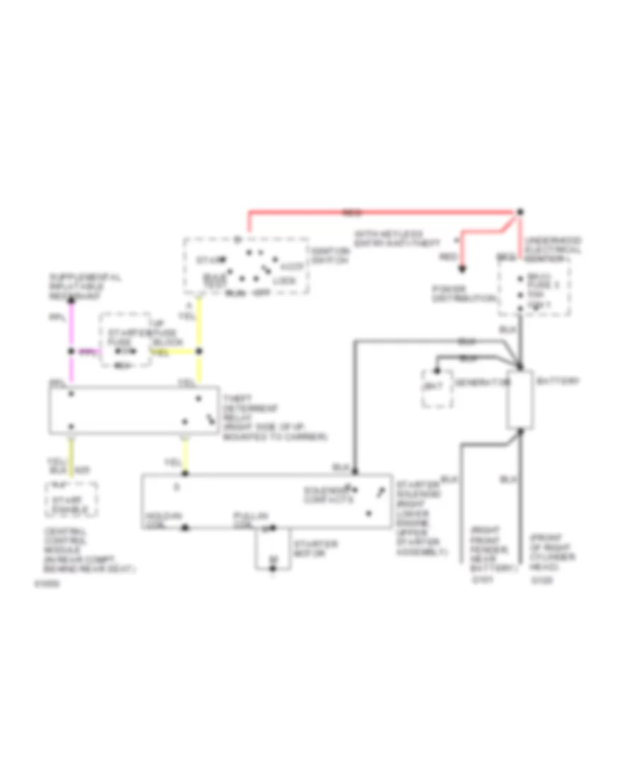
STARTING/CHARGING Charging Wiring Diagram for Cadillac Fleetwood 1994 List of elements for Charging Wiring Diagram for Cadillac Fleetwood 1994: 25 #16 #25 (front of right cylinder head) (right front fender, near battery) (solid state) Bat Battery Charge warning ind. Field (rotor) G101 G120 Gen fuse 10a Generator (right side of engine, forward of right valve cover) Hot in run Hvac ign fuse 10a I/p fuse block Instrument cluster Power distribution Rectifier bridge Regulator Secondary engine cooling fan relay Starter solenoid (right lower engine, upper starter assembly) Stator Turn on input Voltage sensing input Starting Wiring Diagram for Cadillac Fleetwood 1994 List of elements for Starting Wiring Diagram for Cadillac Fleetwood 1994: 31 #24 (front of right cylinder head) (right front fender, near battery) 10a Accy Bat Battery Bulb test Central control module (in rear compt, behind rear seat) G101 G120 Generator Hold-in coil I/p fuse block Ignition switch Lock Maxi- fuse 3 50a ign 1 Off Power distribution Pull-in coil Red Run Solenoid contacts Start Start enable Starter fuse Starter motor Starter solenoid (right lower engine, upper starter assembly) Theft deterrent relay (right side of i/p, mounted to carrier) Underhood electrical center With keyless entry/anti-theft
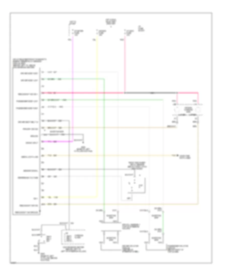
SUPPLEMENTAL RESTRAINTS Supplemental Restraint Wiring Diagram for Cadillac Fleetwood 1994 List of elements for Supplemental Restraint Wiring Diagram for Cadillac Fleetwood 1994: 43 (lower) (upper) 8.45 k A10 Air bag fuse 15a Air bag warning inds B10 Computer data lines Comvenience center (behind left i/p, left of steering column) Crank input Driver inflator module (center of steering wheel) Driver seat belt in Driver side "high" Driver side "low" Front end sheet metal sensor (below hood latch mechanism) G200 (base of left "a" pillar kick pad) G200 (base of left "a" pillar, behind kick pad) Ground Hot in run, bulb test or start Hot in start I/p fuse block I/p indic fuse 10a Ign 1 Inflatable restraint diagnostic energy reserve (w/ sensor) module (sdm) (behind left i/p, above convenience center) Nca Passenger inflator module (below right i/p top cover) Passenger side "high" Passenger side "low" Pnk Primary sir ind Redundant ind ground Redundant ind ign 1 Redundant sir ind Reference voltage Seat belt input Seat belt sw Sensor signal Serial data line Shorting bar Sir coil assembly (top of steering column) Starter fuse 10a Tan Warning alarm
TRANSMISSION
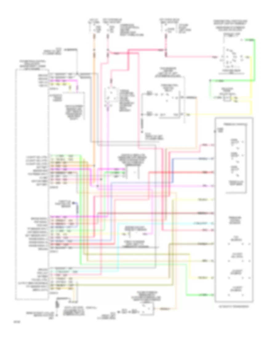
5.7L 5.7L (VIN P), Transmission Wiring Diagram, 4L60-E for Cadillac Fleetwood 1994 List of elements for 5.7L (VIN P), Transmission Wiring Diagram, 4L60-E for Cadillac Fleetwood 1994: 91 (attached to i/p carrier, right of steering column) (engine compt, under (front of engine (in power steering line, (near base of steering column, on column) (no loc avail) (partial) 1-2 shift 1-2 shift sol ctrl 2-3 shift 2-3 shift sol ctrl 3-2 cont sol (pwm) 3-2 shift sol ctrl 5v ref Above windshield Air cleaner) Automatic trans- mission Automatic transmission Back-up lamp Battery Brake signal Case gnd Chime 10a Comp, next to Conn a Conn b Conn c Conn d Convenience center (left of i/p, left of steering column) Data link conn Diode Ect sensor input Engine coolant temp (ect) sensor Forward gear sw G110 (front left cylinder head) G110 (front of left cylinder head) Ground Hot at all times Hot in run, bulb test or start Hot in run,bulb test or start I/p fuse block (left side of i/p) Ign feed Ignition feed Isolation Manifold absolute Map sens signal Mode sw a Mode sw b Mode sw c Module (pcm) Near power steering Output service enable P/s press input Park/neutral Park/neutral position and backup lamp sw assembly Pcm/ fuel 15a Pcm/ ign 10a Pcs high Pcs low Pnk Pnp signal Position Power steering Powertrain control Press sw manifold Pressure (map) sensor (rear of engine comp Pressure control solenoid Pressure sw Range signal a Range signal b Range signal c Red Relay Sensor gnd Serial data Solenoid Tan Tcc Tcc sol ctrl Tft sensor input Thermostat housing) Throttle position (tp) sensor Torque converter clutch (tcc) cruise control release sw (on brake pedal bracket) Tp sensor input Trans fluid temp sens Underhood (u/h) electrical center (engine comp, right wheelhouse) Unit) Vehicle speed sensor (vss) (left rear of transmission, near prop shaft) Vss (hi) Vss (lo) Wiper motor)
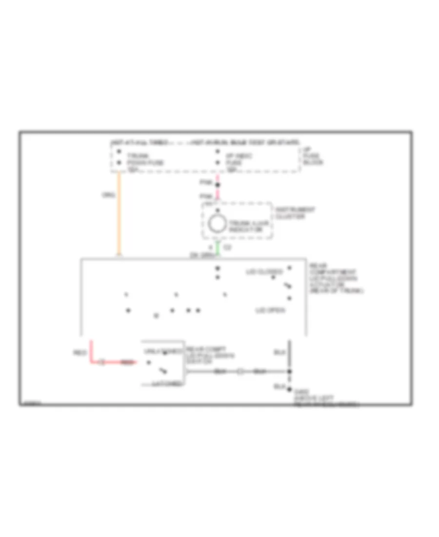
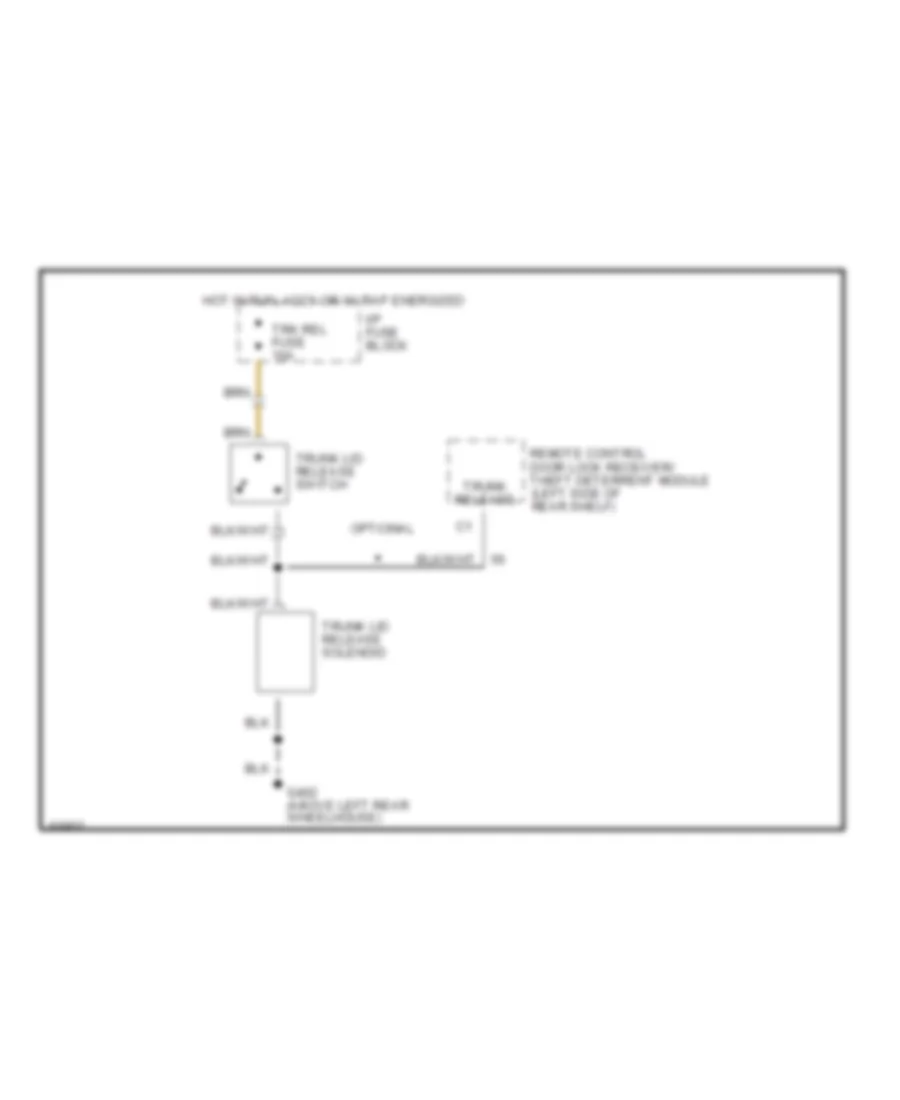
TRUNK, TAILGATE, FUEL DOOR Trunk Pull-Down Wiring Diagram for Cadillac Fleetwood 1994 List of elements for Trunk Pull-Down Wiring Diagram for Cadillac Fleetwood 1994: 16 G402 (above left rear wheelhouse) Hot at all times Hot in run, bulb test or start I/p fuse block I/p indic fuse 10a Instrument cluster Latched Lid closed Lid open Pnk Rear compartment lid pull-down actuator (rear of trunk) Rear compt lid pull-down switch Red Trunk ajar indicator Trunk pdwn fuse 15a Unlatched Trunk Release Wiring Diagram for Cadillac Fleetwood 1994 List of elements for Trunk Release Wiring Diagram for Cadillac Fleetwood 1994: 9 G402 (above left rear wheelhouse) Hot in run, accy or w/ rap energized I/p fuse block Optional Remote control door lock receiver/ theft deterrent module (left side of rear shelf) Trk rel fuse 10a Trunk lid release solenoid Trunk lid release switch Trunk release
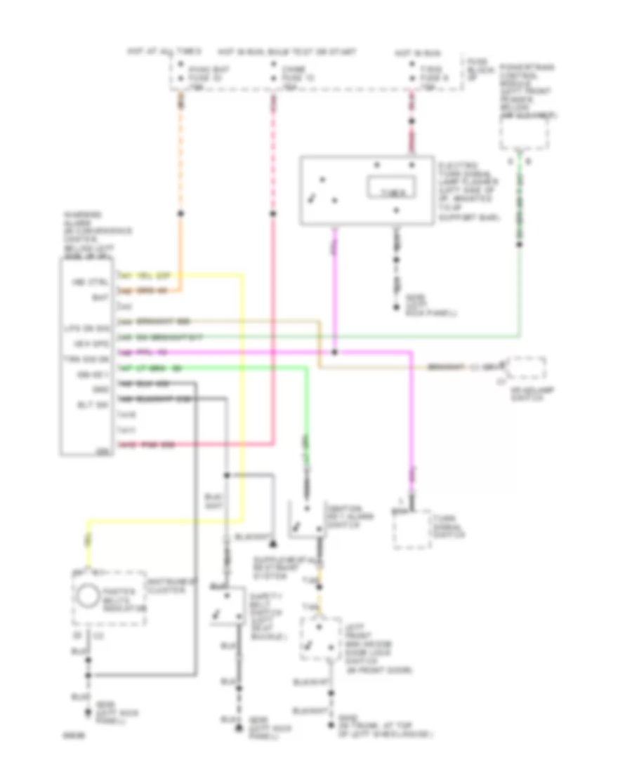
WARNING SYSTEMS Warning System Wiring Diagrams for Cadillac Fleetwood 1994 List of elements for Warning System Wiring Diagrams for Cadillac Fleetwood 1994: 35 A10 A11 A12 Bat Blt sw Chime fuse 13 10a Electric turn signal lamp flasher (left side of i/p, mounted to i/p support bar) Fasten belts indicator Fuse block: i/p G200 (left kick panel) G402 (in trunk, at top of left wheelhouse) Gnd Headlamp switch Hot at all times Hot in run Hot in run, bulb test or start Hvac bat fuse 33 10a Ign Ign key Ignition key alarm switch Ind ctrl Instrument cluster Left front mini wedge door lock switch (in front door) Lps on sig Nca Pnk Powertrain control module (left front fender, below air cleaner) Safety belt switch (left seat buckle) T/sig fuse 6 15a Tan Timer Trn sig on Turn signal switch Veh spd Warning alarm (in convenience center, below left side of i/p)
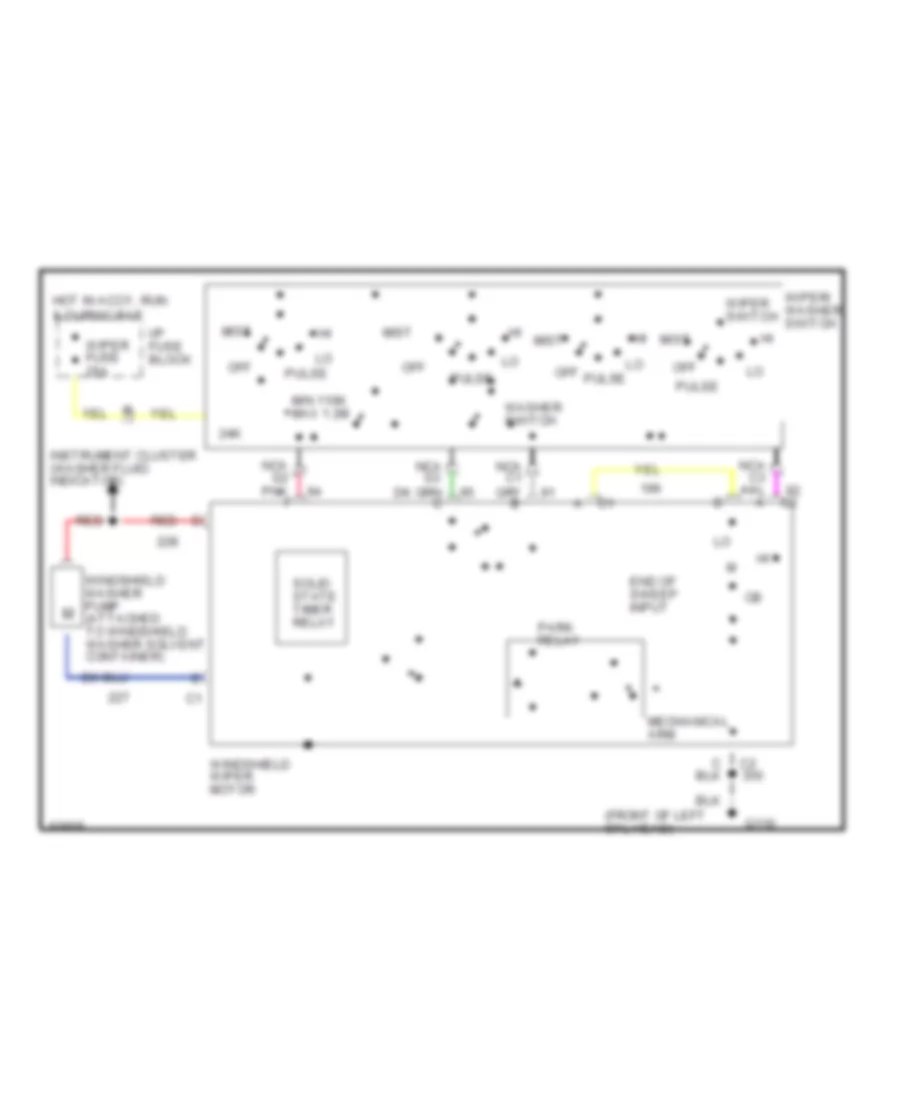
WIPER/WASHER Interval Wiper/Washer Wiring Diagram for Cadillac Fleetwood 1994 List of elements for Interval Wiper/Washer Wiring Diagram for Cadillac Fleetwood 1994: 22 (front of left cyl head) 24k End of sweep input G110 Hot in accy, run & during rap I/p fuse block Instrument cluster (washer fluid indicator) Mechanical arm Min 110k max 1.2m Mist Nca g2 pnk f Off Park relay Pulse Red Solid state timer relay Washer switch Windshield washer pump (attached to windshield washer solvent container) Windshield wiper motor Wiper fuse 25a Wiper switch Wiper/ washer switch