SUPPLEMENTAL RESTRAINTS
Supplemental Restraint Wiring Diagram for Isuzu Trooper LS 1995
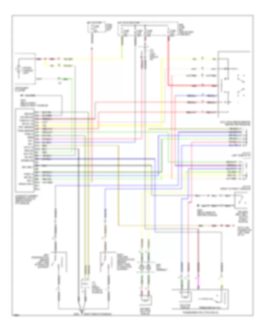
List of elements for Supplemental Restraint Wiring Diagram for Isuzu Trooper LS 1995:
- (right side of console)
- A10
- A11
- A12
- Air bag warning light
- B10
- B11
- B12
- Crank input
- Dash fuse box
- Data i/o
- Data link connector (left side of i/p)
- Diagnostic energy reserve module (behind front of console)
- Dreq
- Dri 36 vlr
- Dri hi
- Driv belt
- Driv sensor
- Driver's inflator module
- Driver's seat belt switch (in belt buckle)
- Dual pole arming sensor (behind center of i/p)
- Fuse c-1 10a
- Fuse c-21 10a
- Fuse c-22 10a
- Fuse c-23 10a
- Fuse c-24 10a
- G302
- G302 (below rear of center console)
- G302 (below right side of front console)
- Ground
- Hot in on or start
- Hot in start
- I-37
- Ign 1
- Ind ctrl
- Ind ground
- Ind ign1
- Inflator module
- Instrument cluster
- J/c (u-4) (front of front console)
- J/c (u-7) (left side of i/p)
- Left discrimination sensor (left side of radiator support)
- Pass 36 vlr
- Pass hi
- Pass lo
- Pass sensor
- Passenger's inflator module
- Pnk
- Pressure switch
- Red
- Right forward discrimination sensor (right side of radiator support)
- Spare/lps
- Srs coil assembly
- Srs fuse box (above dash fuse box)
 Čeština
 Deutsch
 Ελληνικά
 English
 English
 Español
 Suomi
Suomi Français
 Français
 עברית
עברית Hrvatski
 Magyar
 Italiano
 日本語
日本語 한국어
한국어 Nederlands
 Polski
 Português
 Português
 Română
 Русский
 Slovenčina
 Slovenščina
 Svenska
 Türkçe
 中文 (中国)
 Dansk
Dansk