СИСТЕМА АНТИБЛОКИРОВОЧНОЙ ТОРМОЗНОЙ СИСТЕМЫ ABS
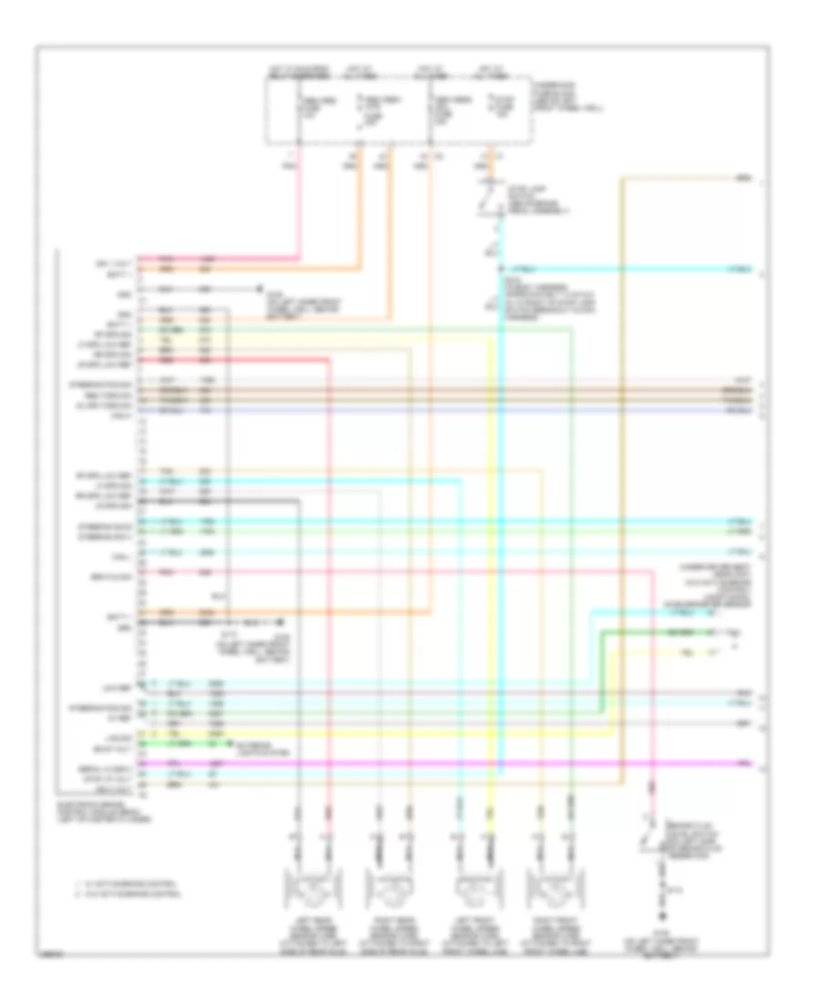
Электросхема антиблокировочной тормозной системы АБС (ABS) (1 из 2) для Hummer H3 2007
Электросхема антиблокировочной тормозной системы АБС (ABS) (1 из 2) для Hummer H3 2007 - Список элементов:
- (under driver seat near c307) (w/o active brake control) longitudinal accelerometer sensor
- 5v ref
- Abs/vses fuse 10a
- Abs/vses1 -mtr
- Abs/vses2 -sol fuse 30a
- Batt +
- Bkup volt
- Brake fluid level switch (on left side of brake fluid reservoir)
- Brk fld sig
- Can h
- Can l
- Dlvrd torq sig
- Electronic brake control module (ebcm) (left of master cylinder)
- Exterior lights system
- Fuse 40a
- G105 (on left inner front wheel well, behind battery)
- Gnd
- Grd
- Hot at all times
- Hot w/ run/crnk relay energized
- Ign 1 volt
- Ign 3 volt
- Las sig
- Left front wheel speed sensor (wss) (attached to left front wheel hub)
- Left rear wheel speed sensor (wss) (attached to left side of rear axle)
- Lf spd low ref
- Lf spd sig
- Low ref
- Lr spd low ref
- Lr spd sig
- Nca
- Pnk
- Red
- Req torq sig
- Rf spd low ref
- Rf spd sig
- Right front wheel speed sensor (wss) (attached to right front wheel hub)
- Right rear wheel speed sensor (wss) (attached to right side of rear axle)
- Rr spd low ref
- Rr spd sig
- S110
- Serial class 2
- Steering pos sig
- Steering sig a
- Steering sig b
- Stop fuse 15a
- Stop lamp switch (above brake pedal assembly)
- Stop lp volt
- Tan
- Underhood fuse block (above left front wheel well)
- W/ active brake control
- W/o active brake control
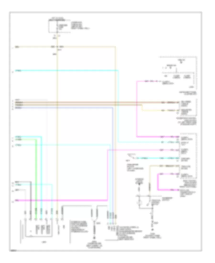
Электросхема антиблокировочной тормозной системы АБС (ABS) (2 из 2) для Hummer H3 2007
Электросхема антиблокировочной тормозной системы АБС (ABS) (2 из 2) для Hummer H3 2007 - Список элементов:
- A17
- A31
- A37
- A38
- A39
- A41
- Abs ind
- Accessory switch
- Body control module (bcm) (behind right front kick panel)
- Brake ind
- Can h
- Can l
- Class 2 (ebcm)
- Class 2 serial data
- Data link connector (dlc) (left side of dash)
- Delivered torque signal
- G106 (on right inner front wheel well)
- G300 (under driver seat carpet, on floor board)
- Gnd
- Hot w/ hvac relay energized
- Ign
- Ign 3 volt
- Instrument panel cluster (ipc)
- Interior lights system
- Logic
- Park brake switch (left lower side of dash)
- Park brk sw sig
- Powertrain control module (pcm) (at left front side of engine compt)
- Requested torque signal
- S141
- S205
- S300
- Steering pulse sig
- Steering sig a
- Steering sig b
- Steering wheel position sensor (w/ active brake control) (near base of steering column)
- Stop lp volt
- Trac ctrl sw sig
- Traction control switch
- Underhood fuse block (above left front wheel well)
- Vses/abs fuse 10a
- Yaw rate/lateral & longitudinal accelerometer sensor (w/ active brake control) (under driver seat near c307)

 Čeština
 Deutsch
 Ελληνικά
 English
 English
 Español
 Suomi
Suomi Français
 Français
 עברית
עברית Hrvatski
 Magyar
 Italiano
 日本語
日本語 한국어
한국어 Nederlands
 Polski
 Português
 Português
 Română
 Русский
 Slovenčina
 Slovenščina
 Svenska
 Türkçe
 中文 (中国)