СИСТЕМА УПРАВЛЕНИЯ ДВИГАТЕЛЯ
2.6L
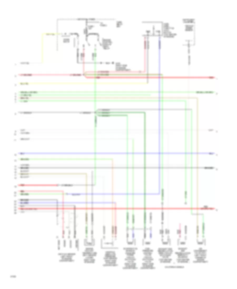
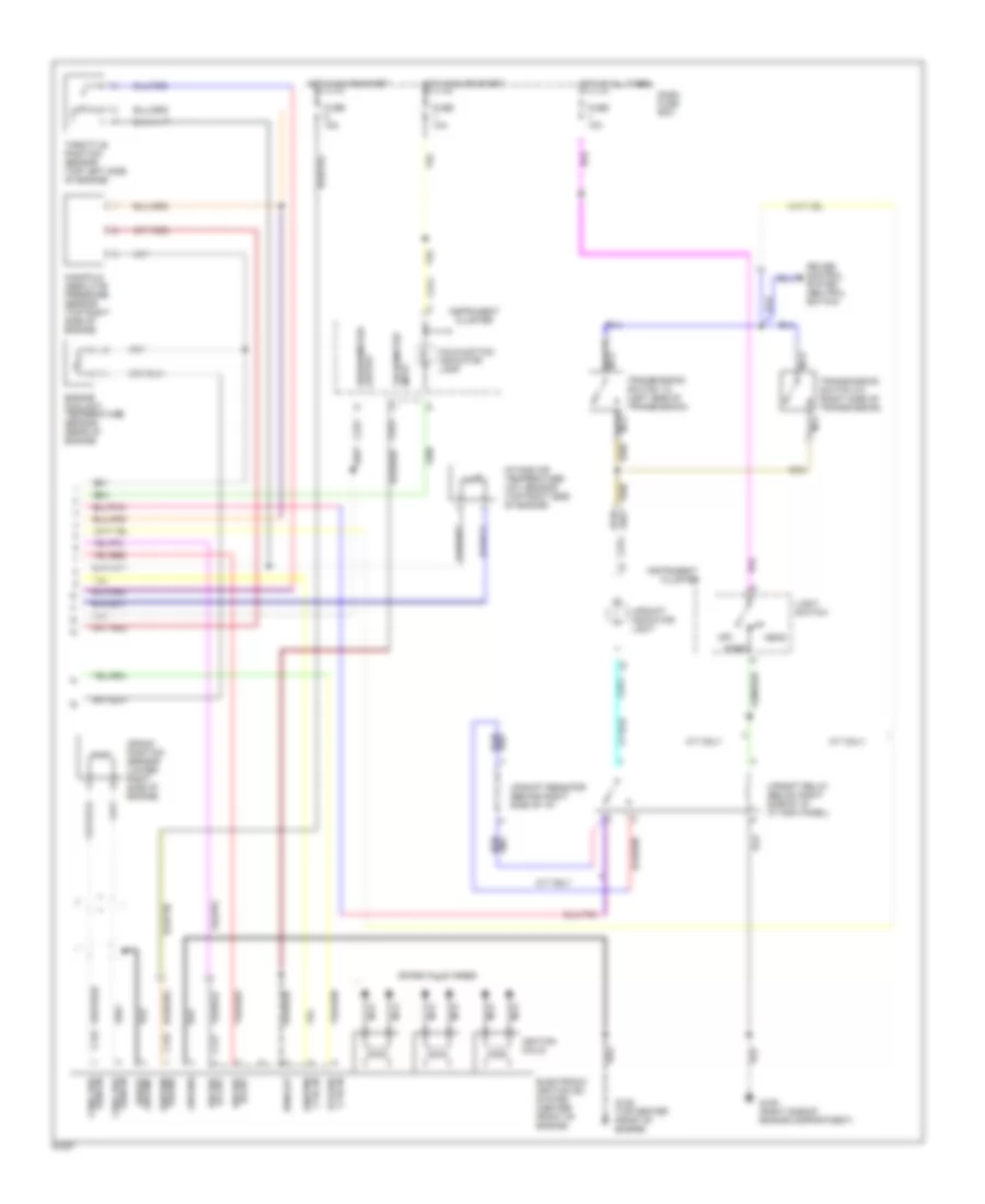
2.6L, Электросхема системы управления двигателя (1 из 3) для Isuzu Rodeo LS 1994


2.6L, Электросхема системы управления двигателя (1 из 3) для Isuzu Rodeo LS 1994 - Список элементов:
- (at left kick panel)
- (below left side of i/p at kick panel)
- (top of engine)
- A/c-switch
- Air conditioning system
- Air vsv control
- Braided
- C210
- C211
- Connector
- Crank signal
- Crankshaft pos sens
- Dash fuse box
- Data link
- Diagnostic test terminal
- Dlc serial data
- Ect sensor ground
- Ect sensor input
- Egr cut vsv control
- Egr duty sol control
- Engine control module (ecm)
- Engine speed input
- Evap canister vsv ctrl
- Fuel inj #1 control
- Fuel inj #2 control
- Fuel inj #3 control
- Fuel inj #4 control
- Fuel injector #1
- Fuel injector #2
- Fuel injector #3
- Fuel injector #4
- Fuel pres ctrl vsv
- Fuse 11 10a
- Fuse 3 10a
- Fuse 7 10a
- Fuse 8 10a
- G120 (right side of engine)
- Ground
- Ho2s input
- Ho2s shield ground
- Hot at all times
- Hot in on or start
- Hot in start
- Ignition power
- Instrument cluster
- Maf sensor ground
- Maf sensor input
- Maf sensor power
- Mafs shield cround
- Malfunction indicator lamp (mil)
- Map sens grd
- Map sens input
- Map sens ref volt.
- Memory power
- Mil control
- Monitor
- Not
- Red
- Used
- Vehicle speed input
- Wot sw idle position
- Wot sw-wot position
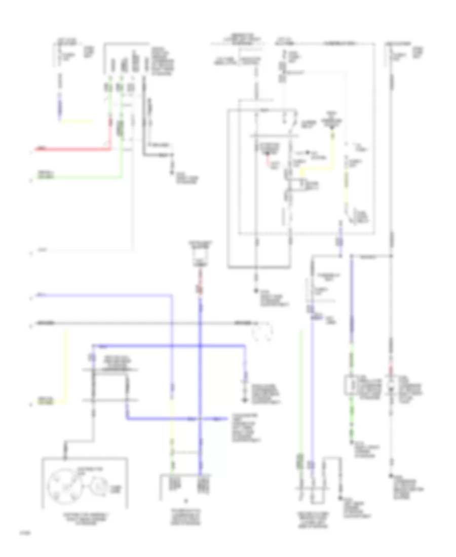
2.6L, Электросхема системы управления двигателя (2 из 3) для Isuzu Rodeo LS 1994
2.6L, Электросхема системы управления двигателя (2 из 3) для Isuzu Rodeo LS 1994 - Список элементов:
- (left front corner of engine compartment)
- (lower right side of engine)
- (right side of engine compartment)
- (top center of engine)
- Air flow sensor (left front of engine compartment)
- Air management valve (amv)
- Braided
- C274
- California models
- Diode box b
- Engine control module (ecm) relay
- Engine coolant temperature (ect) sensor
- Evaporative emission canister purge vacuum switching valve
- Exhaust gas recirculation (egr) duty solenoid
- Exhaust gas recirculation (egr) vacuum switching valve
- Fuel pressure control valve vacuum switching valve
- Fuse 1 15a
- Fuse/ relay box
- G105 (right side of engine compartment)
- Ground
- Hot at all times
- Idle
- Instrument cluster
- Manifold absolute pressure (map) sensor (right side of engine compartment)
- Not used
- Output
- Power
- Red
- To fuse 2
- Vehicle speed sensor
- Wide open throttle (wot) switch (top center of engine)
- Wot
2.6L, Электросхема системы управления двигателя (3 из 3) для Isuzu Rodeo LS 1994
2.6L, Электросхема системы управления двигателя (3 из 3) для Isuzu Rodeo LS 1994 - Список элементов:
- (right rear corner oif engine)
- A/c system
- Air regulator (underside of vehicle, right side of engine)
- Braided
- C274
- Charge relay
- Crank position sensor (underside of vehicle, right rear of engine)
- Dash fuse box
- Diode box a
- Distributor assembly
- Distributor cap
- From oil pressure switch
- Fuel pump (underside of vehicle, right front of fuel tank)
- Fuel pump relay
- Fuse 2 20a
- Fuse 5 10a
- Fuse 5 20a
- Fuse 6 10a
- Fuse 9 15a
- Fuse/relay box
- G104 left rear corner of engine compartment
- G105 (right side of engine compartment)
- G119 (right front corner of engine)
- G120 (right side of engine)
- G409 (underside of vehicle behind center of rear bumper)
- Generator (lower left front of engine)
- Ground
- Heated oxygen sensor (ho2s) (lower left side of engine)
- Hot at all times
- Hot in on or start
- Hot in start
- Ignition coil (center rear of engine compartment)
- Indicator control
- Instrument cluster
- Main fuse 1 60a
- Not used
- Power
- Power signal input
- Power switch (underside of vehicle, right side of engine)
- Primary
- Primary winding control
- Radio noise suppressor (center rear of engine compartment)
- Red
- Reference voltage
- Secondary
- Signal output
- Starting/ charging
- System
- Tachometer test connector (not used) (right side of engine compartment)
- Timer core
- To fuse 1
- Voltage regulator
3.2L
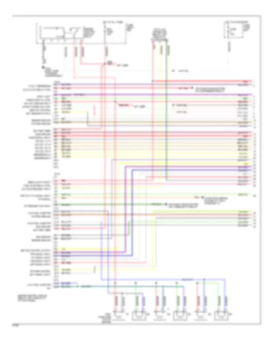
3.2L SOHC, Электросхема системы управления двигателя (1 из 3) для Isuzu Rodeo LS 1994
3.2L SOHC, Электросхема системы управления двигателя (1 из 3) для Isuzu Rodeo LS 1994 - Список элементов:
- "check eng" mil ctrl
- (m/t only)
- 1 & 2 fuel injector
- 3 & 4 fuel injector
- 5 & 6 fuel injector
- 5 volt reference
- A/c clutch relay ctrl
- A/c request sig input
- A10
- A11
- A12
- Air conditioning system (a/c compressor relay)
- Air conditioning system (a/c thermostat relay)
- B10
- B11
- B12
- Battery feed
- Bypass control
- C10
- C11
- C12
- C13
- C14
- C15
- C16
- C218
- C219
- Canist purge vsv ctrl
- D10
- D11
- D12
- D13
- D14
- D15
- D16
- Dash fuse box
- Data link connector (below left side of i/p, at kick panel)
- Dlc diag request input
- Ecm fuse 30a
- Ecm ground
- Ect sensor output
- Ect signal input
- Egr vsv control
- Engine control module (below left side of i/p, at kick panel)
- Engine control module relay
- Fuel injectors (top of engine)
- Fuel pump relay ctrl
- Fuse 10a
- Fuse/ relay box
- G105 (right side of engine compartment)
- Ho2s ground
- Ho2s signal input
- Hot at all times
- Hot in on or start
- Iac coil "a" hi
- Iac coil "a" lo
- Iac coil "b" hi
- Iac coil "b" lo
- Iat signal input
- Ign voltage sig input
- Ignition control output
- Map signal input
- N/a
- Not used
- P/n signal
- Psp switch signal input
- Red
- Reference hi
- Reference lo
- Sensor ground
- Serial data in/out
- Shift light
- Starting/charging system (a/t only) (diode box a)
- System ground
- Tps signal input
- Vss signal input
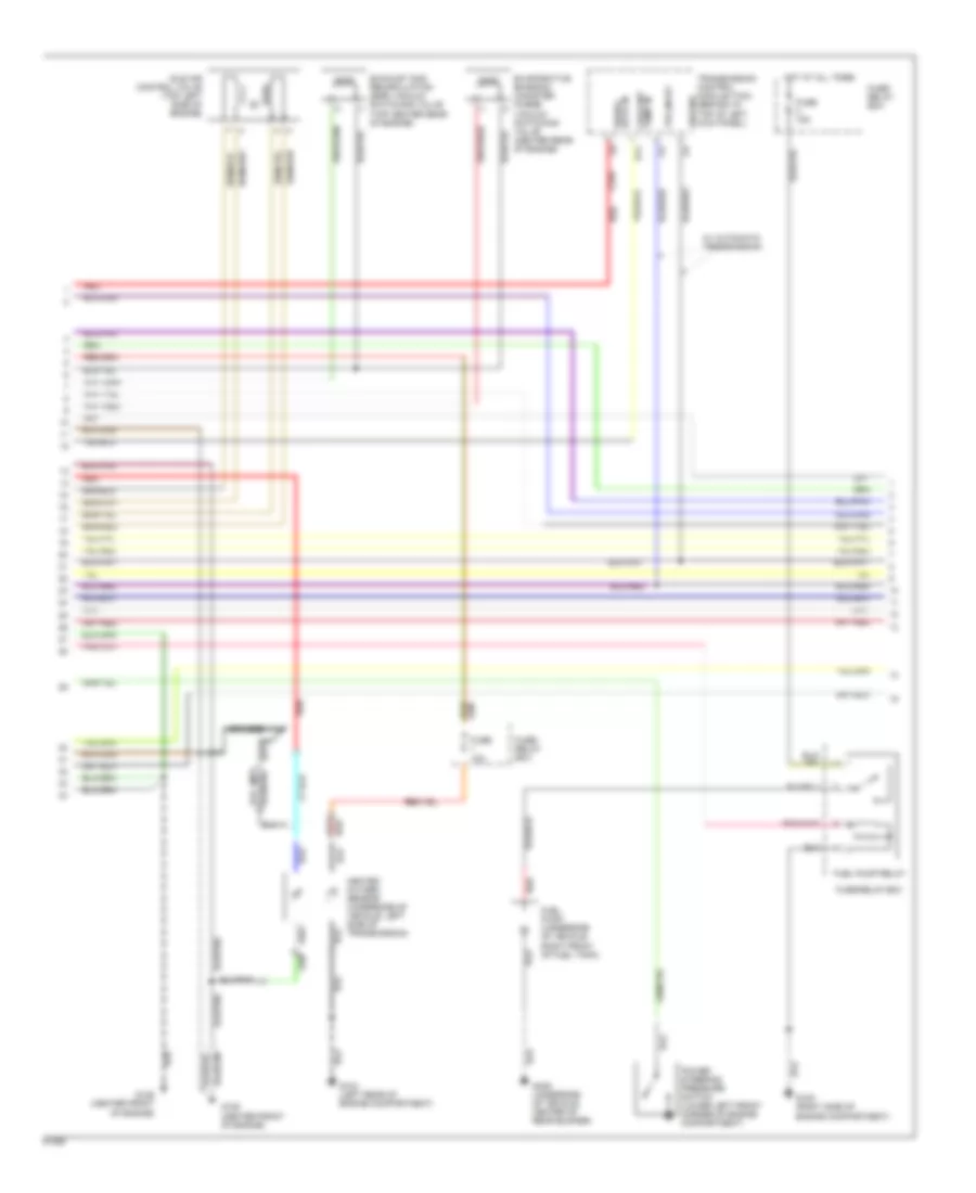
3.2L SOHC, Электросхема системы управления двигателя (2 из 3) для Isuzu Rodeo LS 1994
3.2L SOHC, Электросхема системы управления двигателя (2 из 3) для Isuzu Rodeo LS 1994 - Список элементов:
- (a/t)
- (m/t)
- Braided
- C234
- Coolant temp in
- D14
- Data in serial
- Evaporative emission canister purge vacuum switching valve (center rear of engine)
- Exhaust gas recirculation (egr) vacuum switching valve (top center rear of engine)
- Fuel pump (underside of vehicle right front of fuel tank)
- Fuel pump relay
- Fuse 10a
- Fuse 15a
- Fuse/ relay box
- Fuse/relay box
- G104 (left rear of engine compartment)
- G105 (right side of engine compartment)
- G125 (center front of engine)
- G409 (underside of vehicle, center of rear bumper)
- Ground
- Heated oxygen sensor (underside of vehicle, left side of transmission)
- Hot at all times
- Idle air control valve (top left side of engine)
- Power steering pressure switch (lower left front corner of engine compartment)
- Red
- Tps input
- Transmission control module (tcm) (behind i/p, top of left kick panel)
- W/ automatic transmission
3.2L SOHC, Электросхема системы управления двигателя (3 из 3) для Isuzu Rodeo LS 1994
3.2L SOHC, Электросхема системы управления двигателя (3 из 3) для Isuzu Rodeo LS 1994 - Список элементов:
- C176
- C177
- C178
- C274
- C275
- Cluster
- Crank position sensor (lower right side of engine)
- Crnk pos sens in
- Cruise control system (neutral switch)
- Ctrl in bypass
- Ctrl in ignition
- Dash fuse box
- Electronic ignition (ei) system (center front of engine)
- Engine coolant temperature sensor (rear of engine)
- Fuse 10a
- Fuse 15a
- G105 (right side of engine compartment)
- G125 (top center front of engine)
- Ground
- Head
- Hi out ign ref
- Hot at all times
- Hot in on or start
- Ignition coils
- Instrument
- Instrument cluster
- Intake air temperature (iat) sensor (top right side of engine)
- Light switch
- Lo out ign ref
- M/t only
- Malfunction indicator lamp
- Manifold absolute pressure sensor (top right side of engine)
- Nca
- Off
- Output speedometer
- Park
- Power ignition
- Rpm out
- Sens in crnk pos
- Shield ground
- Spark plug wires
- Tachometer input
- Throttle position sensor (top left side of engine)
- Transmission switch 1-2 (left side of transmission)
- Transmission switch 3-4 (right side of transmission)
- Upshift indicator light
- Upshift relay (below right side of i/p, at kick panel)
- Upshift resistor (behind right side of i/p)

 Čeština
 Deutsch
 Ελληνικά
 English
 English
 Español
 Suomi
Suomi Français
 Français
 עברית
עברית Hrvatski
 Magyar
 Italiano
 日本語
日本語 한국어
한국어 Nederlands
 Polski
 Português
 Português
 Română
 Русский
 Slovenčina
 Slovenščina
 Svenska
 Türkçe
 中文 (中国)