
 Čeština
 Deutsch
 Ελληνικά
 English
 English
 Español
 Suomi
Suomi Français
 Français
 עברית
עברית Hrvatski
 Magyar
 Italiano
 日本語
日本語 한국어
한국어 Nederlands
 Polski
 Português
 Português
 Română
 Русский
 Slovenčina
 Slovenščina
 Svenska
 Türkçe
 中文 (中国)

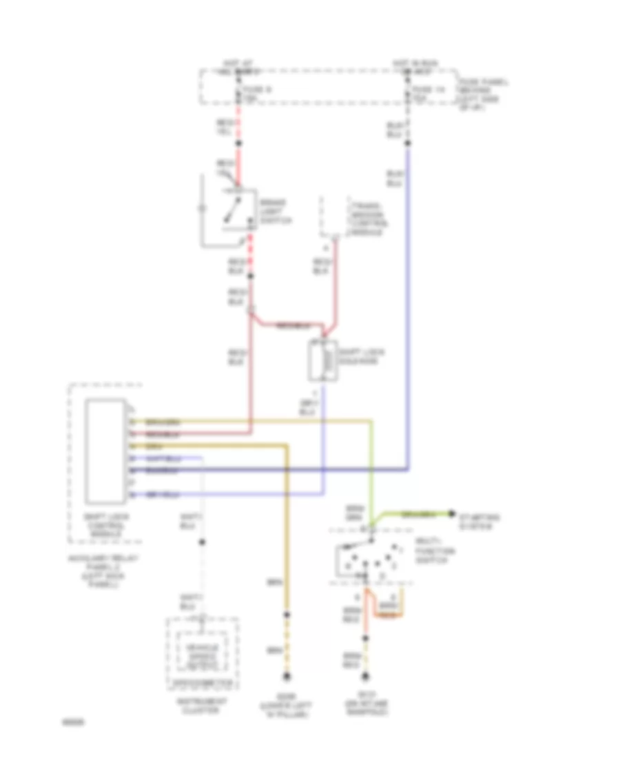
SHIFT INTERLOCK
Shift Interlock Wiring Diagram for Audi 100 CS Quattro 1994
List of elements for Shift Interlock Wiring Diagram for Audi 100 CS Quattro 1994:

ANTI-THEFTAIR CONDITIONINGANTI-LOCK BRAKESCRUISE CONTROLCOMPUTER DATA LINESDEFOGGERSENGINE PERFORMANCECOOLING FANELECTRONIC POWER STEERINGGROUND DISTRIBUTIONHORNEXTERIOR LIGHTSHEADLIGHTSINSTRUMENT CLUSTERMEMORY SYSTEMSPOWER DOOR LOCKSPOWER DISTRIBUTIONINTERIOR LIGHTSPOWER MIRRORSPOWER SEATSRADIOPOWER WINDOWSPOWER TOP/SUNROOFSUPPLEMENTAL RESTRAINTSSTARTING/CHARGINGTRANSMISSIONTRUNK, TAILGATE, FUEL DOORWARNING SYSTEMSSHIFT INTERLOCKWIPER/WASHER