STARTING/CHARGING
Charging Wiring Diagram for Audi A7 Prestige 2013
 https://portal-diagnostov.com/license.html
Automotive Electricians Portal FZCO
Automotive Electricians Portal FZCO
https://portal-diagnostov.com/license.html
https://portal-diagnostov.com/license.html
Automotive Electricians Portal FZCO
Automotive Electricians Portal FZCO
List of elements for Charging Wiring Diagram for Audi A7 Prestige 2013:
- (right side luggage compt) (w/ start/ stop system) voltage stablizer
- Battery
- Battery interrupt igniter
- Battery jump start terminal
- Battery monitoring control module (on battery)
- Computer data lines system
- Data bus on board diagnostic interface (under center of rear seat)
- Display unit
- Engine controls system
- G624
- G645
- Generator & voltage regulator
- Instrument cluster
- Instrument cluster control module
- Main fuse carrier (in luggage compt on battery)
- Red
- Starter
- Suppressor (in right plenum chamber e-box)
- T17a
- Terminal 30 wire junction (in center plenum chamber)
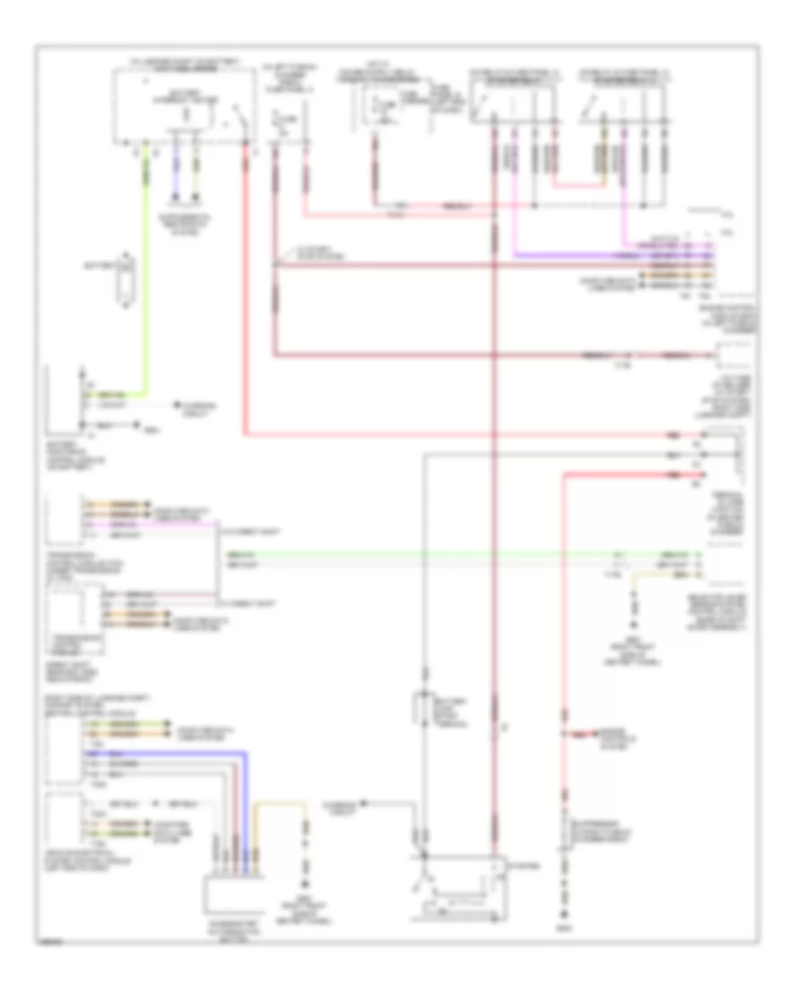
Starting Wiring Diagram for Audi A7 Prestige 2013
List of elements for Starting Wiring Diagram for Audi A7 Prestige 2013:
- (in left plenum chamber e-box) fuse panel a
- (in luggage compt on battery) main fuse carrier
- (on relay & fuse panel a) starter relay
- (on relay & fuse panel a) starter relay 2
- (right side of luggage compt) comfort system central control module
- 16a
- 3.0l
- 4.0l
- Access/start authorization button
- Battery
- Battery interrupt igniter
- Battery jump start terminal
- Battery monitoring control module (on battery)
- Charging circuit
- Computer data lines system
- Direct shift gear box (dsg) mechatronic
- Engine control module (ecm) (in left plenum chamber)
- Engine controls system
- Fuse 40a
- Fuse 5a
- Fuse carrier
- Fuse panel b (left end of dash)
- G624
- G645
- G687 (right front side of center tunnel)
- Red
- Selector lever sensor system control module (base of shift lever assembly)
- Starter
- Suppressor (in right plenum chamber e-box)
- T16c
- T17a
- T17b
- T32a
- T32g
- T32i
- T91
- T94
- Terminal 30 wire junction (in center plenum chamber)
- Transmission control module
- Transmission control module (tcm) (under transmission oil pan)
- Vehicle electrical system control module (left end of dash)
- Voltage stabilizer (w/ start/ stop system) (right side luggage compt)
- W/ direct shift
- W/ start/ stop system
- W/o direct shift

 Čeština
 Deutsch
 Ελληνικά
 English
 English
 Español
 Suomi
Suomi Français
 Français
 עברית
עברית Hrvatski
 Magyar
 Italiano
 日本語
日本語 한국어
한국어 Nederlands
 Polski
 Português
 Português
 Română
 Русский
 Slovenčina
 Slovenščina
 Svenska
 Türkçe
 中文 (中国)