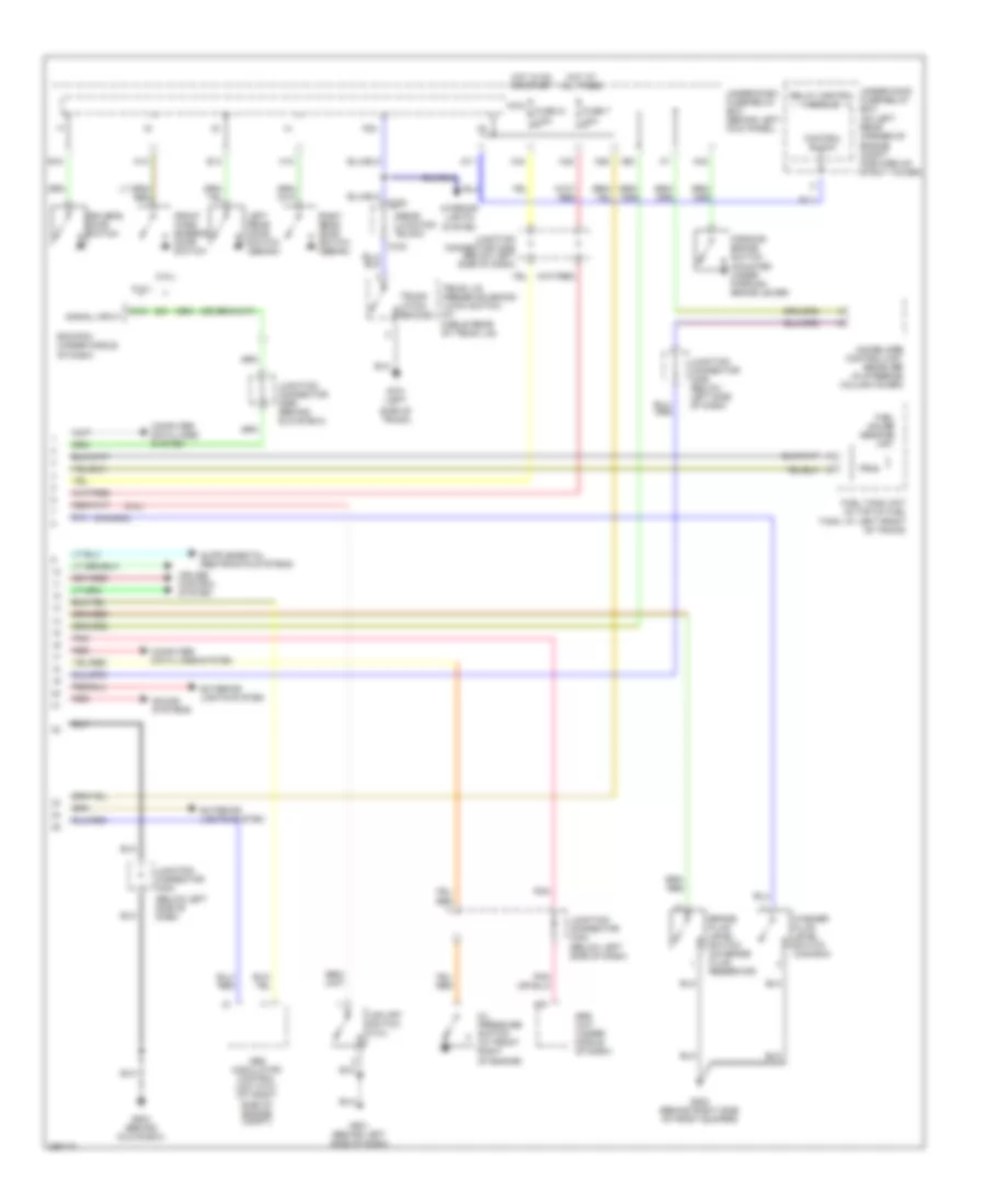
INSTRUMENT CLUSTER
Instrument Cluster Wiring Diagram, Except Hybrid (1 of 2) for Honda Accord Hybrid 2007


List of elements for Instrument Cluster Wiring Diagram, Except Hybrid (1 of 2) for Honda Accord Hybrid 2007:
- (3.0l)
- (canada)
- 10v regulator
- 5v stabilize circuit/controller area network controller
- A/t gear position detection circuit
- A/t gear position dimming circuit
- A/t gear position indicator drive circuit
- Abs ind
- Beeper
- Body controller area network transceiver
- Brake system ind
- Charging system ind
- Compulsory turning-off circuit
- Compulsory turning-on circuit
- Cruise control dimming circuit
- Cruise control ind
- Cruise control main switch ind
- Dash lights brightness controller
- Dial/car graphic/lcd brightness control and dimming circuit
- Drive circuit
- Drl ind
- Encoder sw
- Engine coolant temperature gauge
- Fail-safe circuit
- Fast controller area network transceiver
- Fuel gauge
- G501 (behind left side of dash)
- Gauge control module
- High beam dimming circuit
- High beam ind
- Illumination control circuit
- Immobilizer system ind
- Lcd back light
- Lcd drive
- Left turn signal ind
- Level ind
- Lights on ind
- Low fuel ind
- Low oil pressure ind
- Maintenance required ind
- Mid brightness control and dimming circuit
- Mil ind
- Network controller controller area 5v stabilize circuit/
- Odo/trip a/ trip b/ outside temperature/ check fuel lid/service oil light
- Pnk
- Pointer brightness control and dimming circuit
- Red
- Right turn signal ind
- Seat belt reminder ind
- Security ind
- Security indicator blinking circuit
- Side airbag cut-off ind
- Speedo- meter
- Srs ind
- Tacho- meter
- Vsa activation ind
- Vsa system ind
- Warning drive circuit
- Washer fluid
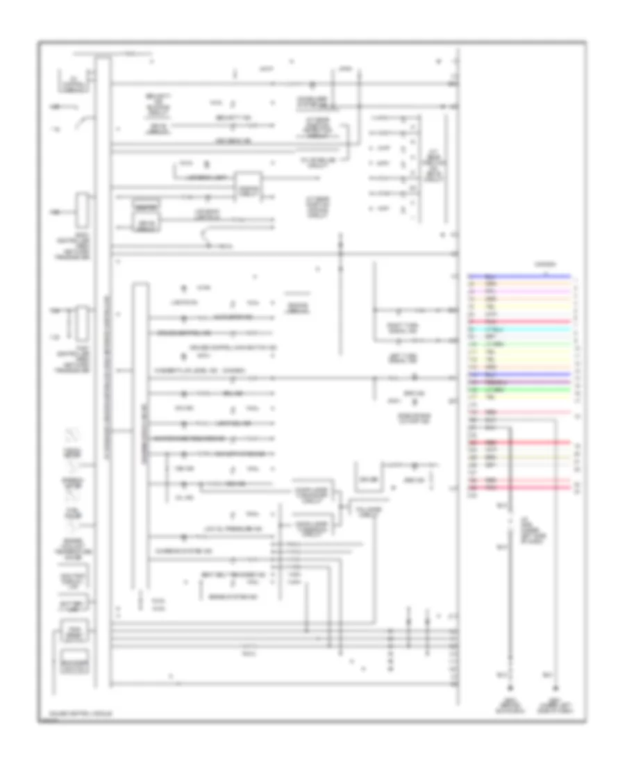
Instrument Cluster Wiring Diagram, Except Hybrid (2 of 2) for Honda Accord Hybrid 2007
List of elements for Instrument Cluster Wiring Diagram, Except Hybrid (2 of 2) for Honda Accord Hybrid 2007:
- (2.4l)
- (3.0l)
- (at right side of engine compt)
- (below left side of dash)
- (below left side of dash)
- (canada)
- A19
- Abs modulator control
- Brake fluid level switch (on brake fluid reservoir)
- C21
- C703
- C752
- Computer data lines system
- Control block
- Cruise control system
- D10
- D11
- Driver's door switch
- E14
- E15
- Ecm/pcm (under middle of dash)
- Exterior lights system
- Front pass- enger's door switch
- Fuel gauge sending unit
- Fuel tank unit (in top of fuel tank, at left front of trunk)
- Fuse 21 7.5a
- Fuse 7 10a
- G202 (behind right side of front bumper)
- G501 (behind left side of dash)
- G503 (behind glove box)
- G701 (left
- H12
- H13
- Hot at all times
- Hot in on or start
- Immobilizer control-unit receiver (in steering column cover)
- Interior lights system
- Junction connector c404
- Junction connector c405 (below left side of dash)
- Junction connector c406 (below left side of dash)
- Junction connector c556 (behind glove box)
- Left rear door switch (sedan)
- Micu
- N28
- N30
- N34
- Oil pressure switch (at front right of engine)
- P24
- Parking brake switch (mounted under parking brake lever)
- Pnk
- Rear junction block
- Red
- Relay control module
- Right rear door switch (sedan)
- Side of trunk)
- Signal input
- Sound systems
- Srs unit (under middle of dash)
- Trunk latch switch
- Trunk lid opener solenoid/ latch switch (at middle rear of trunk lid)
- Under-dash fuse/relay box (behind left kick panel)
- Under-hood fuse/relay box (on left rear corner of engine compt, forward of strut tower)
- Unit
- Vsa off switch (3.0l)
- Washer fluid level switch (canada)
- X34
- X35
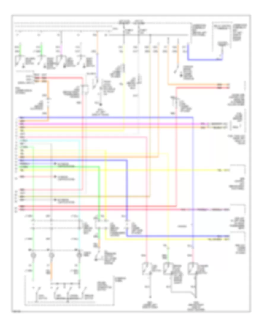
Instrument Cluster Wiring Diagram, Hybrid (1 of 2) for Honda Accord Hybrid 2007
List of elements for Instrument Cluster Wiring Diagram, Hybrid (1 of 2) for Honda Accord Hybrid 2007:
- (canada)
- 10v stabilize circuit
- 5v control circuit
- 5v stabilize circuit/controller area network controller
- A/t gear position detection circuit
- A/t gear position dimming circuit
- A/t gear position ind drive circuit
- Abs ind
- Auto stop ind
- Battery, lcd
- Beeper
- Body controller area network transceiver
- Brake system ind
- Canada
- Charging system ind
- Compulsory turning-off circuit
- Compulsory turning-on circuit
- Cruise control ind
- Cruise control main switch ind
- Dimming circuit
- Drive circuit
- Driver
- Drl ind
- Encoder switch
- Engine coolant temperature gauge
- Eps ind
- Fail-safe circuit
- Fast controller area network transceiver
- Fuel gauge
- G501 (under left side of dash)
- G503 (behind glove box)
- Gauge control module
- High beam ind
- Ima ind
- Immobilizer system ind
- J/c c406 (under left side of dash)
- Lcd back light
- Lcd back lights (4)
- Left turn signal ind
- Lights on
- Low fuel ind
- Low oil pressure ind
- Maintenance required ind
- Mil ind
- Odo/trip/ display, lcd
- Pnk
- Red
- Right turn signal ind
- Seat belt reminder ind
- Security ind
- Security ind blinking circuit
- Side air bag cut-off ind
- Speedo- meter
- Srs ind
- Tacho- meter
- Trip/ reset switch
- Vsa activation ind
- Vsa ind
- Warning drive circuit
- Washer fluid level ind
Instrument Cluster Wiring Diagram, Hybrid (2 of 2) for Honda Accord Hybrid 2007
List of elements for Instrument Cluster Wiring Diagram, Hybrid (2 of 2) for Honda Accord Hybrid 2007:
- A19
- A21
- Brake fluid level switch (at left side of engine compt)
- C11
- Cable reel
- Can h
- Can l
- Canada
- Cancel switch
- Control block
- Cruise control combination switch
- D11
- D18
- Driver's door switch
- E14
- E15
- E26
- E31
- Eps control unit (behind right kick panel)
- Exterior lights system
- Front pass- enger's door switch
- Fuel gauge sending unit
- Fuel tank unit (near left front of trunk)
- Fuse 21 7.5a
- Fuse 7 10a
- G202 (behind right side of front bumper)
- G501 (under left side of dash)
- G701 (at left side of trunk)
- H12
- H13
- Hot at all times
- Hot in on or start
- Immobilizer control-unit receiver (in steering column cover)
- Interior lights system
- J/c c406 (under left side of dash)
- J/c c407 (under left side of dash)
- J/c c408 (under left side of dash)
- J/c c555 (behind front passenger's air bag)
- J/c c556 (behind glove box)
- J/c c557 (behind glove box)
- J/c c558 (behind front passenger's air bag)
- Left rear door switch
- Main switch
- Micu
- N28
- N30
- N34
- Ods unit (in left side of front passenger's seat)
- Oil pressure switch (on lower front of engine)
- P24
- Parking brake switch (under center console)
- Pcm (under middle of dash)
- Pnk
- Red
- Relay control module
- Resume switch
- Right rear door switch
- Set switch
- Signal input
- Srs unit (under middle of dash)
- Steering wheel
- Trunk latch switch (on middle of trunk lid)
- Under-dash fuse/relay box (behind left kick panel)
- Under-hood fuse/relay box (at left side of engine compt)
- Vsa off switch
- Washer fluid level switch
- X34
- X35

 Čeština
 Deutsch
 Ελληνικά
 English
 English
 Español
 Suomi
Suomi Français
 Français
 עברית
עברית Hrvatski
 Magyar
 Italiano
 日本語
日本語 한국어
한국어 Nederlands
 Polski
 Português
 Português
 Română
 Русский
 Slovenčina
 Slovenščina
 Svenska
 Türkçe
 中文 (中国)