AIR CONDITIONING
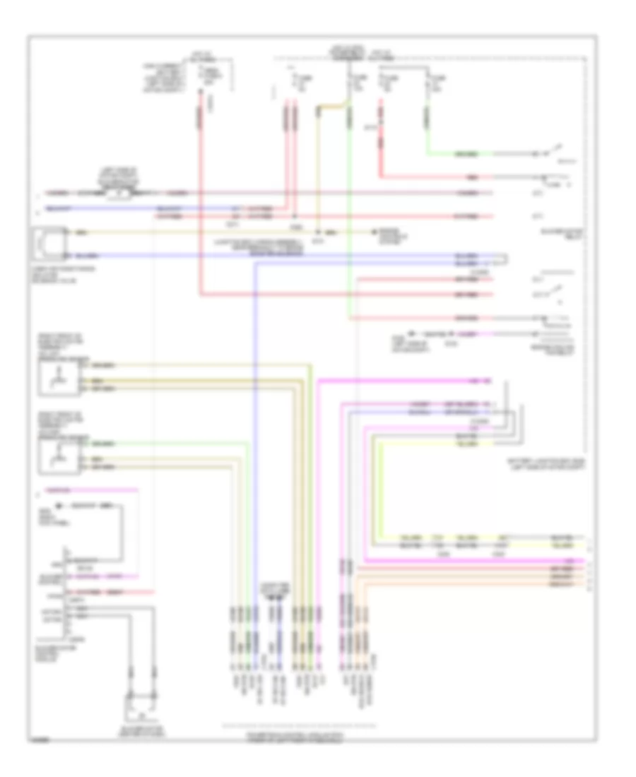
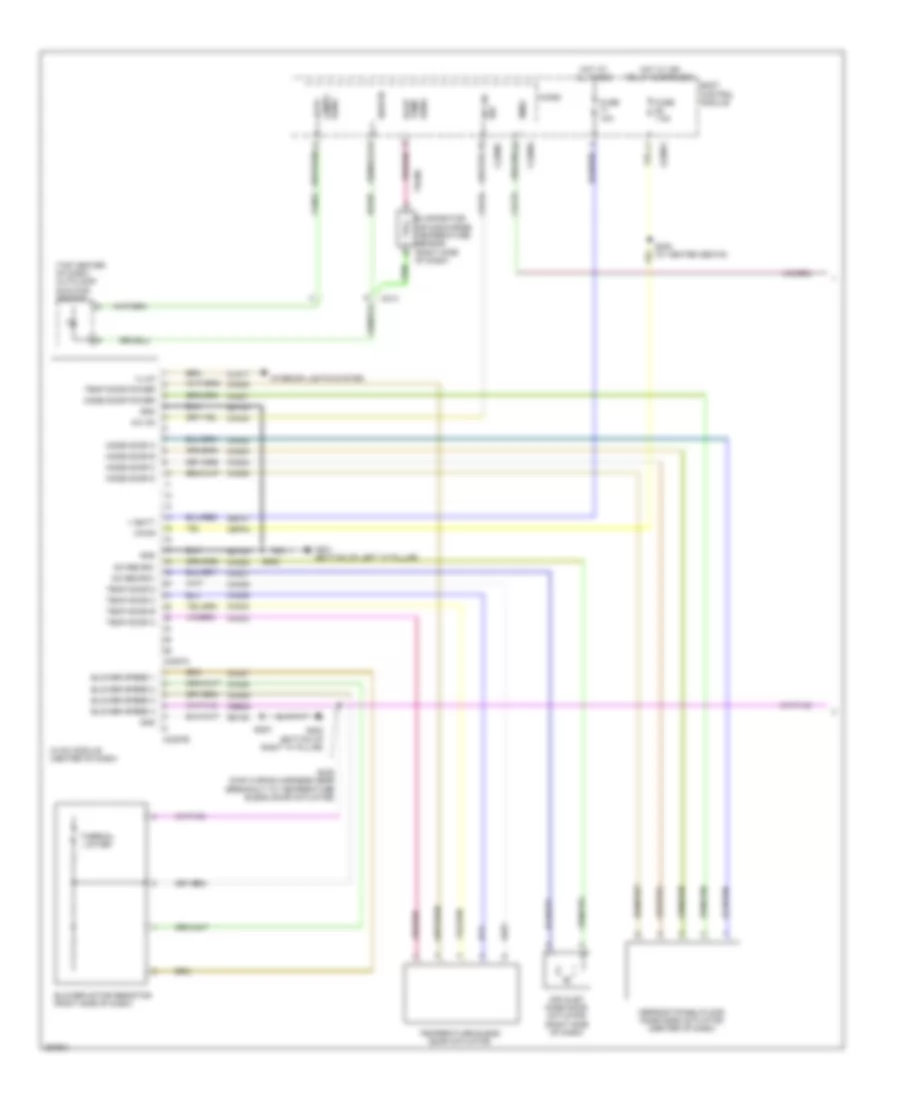
Automatic A/C Wiring Diagram, Electric (1 of 3) for Ford Focus SE 2012
 https://portal-diagnostov.com/license.html
Automotive Electricians Portal FZCO
Automotive Electricians Portal FZCO
https://portal-diagnostov.com/license.html
https://portal-diagnostov.com/license.html
Automotive Electricians Portal FZCO
Automotive Electricians Portal FZCO
List of elements for Automatic A/C Wiring Diagram, Electric (1 of 3) for Ford Focus SE 2012:
- (left center of dash) in-vehicle temperature/ humidity sensor
- (left kick panel) g201
- (top center of dash) autolamp/ sunload sensor
- Air inlet blend door actuator (right side of hvac unit)
- Aspirator gnd
- Auto lamps sens
- Blower control
- Bmrc
- Body control module (lower right side of dash)
- C213
- C2280a
- C2280c
- C2280f
- C228a
- C228b
- Ch123
- Ch201
- Ch202
- Ch203
- Ch204
- Ch205
- Ch206
- Ch207
- Ch208
- Ch209
- Ch210
- Ch211
- Ch212
- Ch213
- Ch214
- Ch215
- Ch227
- Ch228
- Ch229
- Ch230
- Ch231
- Ch237
- Ch238
- Ch239
- Ch240
- Ch241
- Computer data lines system
- Defr a
- Defr b
- Defr c
- Defr d
- Defr pwr
- Defrost mode door actuator (right side of hvac unit)
- Disc floor l sens
- Disc floor r sens
- Disc panel l sens
- Disc panel r sens
- Evap temp sens
- Evaporator temperature sensor
- Fuse 10a
- Gd133
- Gnd
- Hot at all times
- Hs can+
- Hs can-
- Humidity gnd
- Hvac module
- In-car sens
- L sunl sens
- L temp a
- L temp b
- L temp c
- L temp d
- L temp power
- Left center register air discharge temperature sensor (left side of top center dash)
- Left footwell air discharge temperature sensor (left side of hvac unit)
- Left temperature blend door actuator (left side of hvac unit)
- Micro
- Ms can+
- Ms can-
- Pa/fl a
- Pa/fl b
- Pa/fl c
- Pa/fl d
- Pa/fl pwr
- Panel/floor mode door actuator
- R sunl sens
- R temp a
- R temp b
- R temp c
- R temp d
- R temp power
- Recirc a
- Recirc b
- Recirc c
- Recirc d
- Recirc power
- Rh103
- Rh104
- Rh105
- Rh107
- Right center register air discharge temperature sensor (right side of top center dash)
- Right footwell air discharge temperature sensor (right side of hvac unit)
- Right temperature blend door actuator (right side of hvac unit)
- S202
- S246 (main wiring assembly, near breakout to front controls interface module (fcim))
- Sbp27
- Sens
- Sens gnd
- Sigrtn
- Vbatt
- Vdb04
- Vdb05
- Vdb06
- Vdb07
- Vh101
- Vh406
- Vh409
- Vh410
- Vh411
- Vh412
- Vh413
- Vh414
- Vh416
- Vh417
- Vln52
- Vpwr
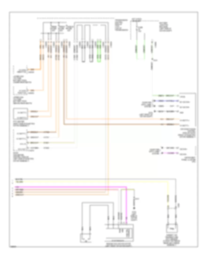
Automatic A/C Wiring Diagram, Electric (2 of 3) for Ford Focus SE 2012
List of elements for Automatic A/C Wiring Diagram, Electric (2 of 3) for Ford Focus SE 2012:
- (junction box wiring assembly, near breakout to brake booster solenoid)
- (left side of motor compt) blower motor relay diode
- (right front of electric motor assembly) a/c high pressure sensor
- (right front of electric motor assembly) a/c low pressure sensor
- A10
- Aat
- Ac sol lsd
- Achp
- Aclp
- Battery junction box (bjb) (left side of motor compt)
- Blower control
- Blower motor (center of dash)
- Blower motor control module
- Blower motor relay
- C1035c
- C1617j
- C175a
- C175b
- C214
- C238
- C297a
- C297b
- C340
- Cabin air conditioning isolator solenoid valve
- Cbb47
- Cet25
- Computer data lines system
- Engine controls system
- Engine cooling fan relay
- Ev hs can+
- Ev hs can-
- Fcv
- Fuse 10a
- Fuse 40a
- Fuse 5a
- G105 (left side of motor compt)
- G202 (right kick panel)
- Gd138
- Gnd
- High current battery junction box (left side of motor compt)
- Hot at all times
- Hot w/ pcm power relay energized
- Hvil sense
- Hvil source
- Lh108
- Mega fuse 8 50a
- Motor+
- Motor-
- Nca
- Powertrain control module (pcm) (front of left front wheelwell)
- Red
- Rh107
- Rh108
- S102
- S115
- S131
- S132
- S203
- Sig rtn
- Vdb04
- Vdb05
- Ve203
- Ve740
- Vh101
- Vh422
- Vpwr
- Vref
- Za113
- Za114
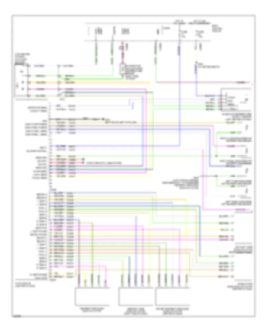
Automatic A/C Wiring Diagram, Electric (3 of 3) for Ford Focus SE 2012
List of elements for Automatic A/C Wiring Diagram, Electric (3 of 3) for Ford Focus SE 2012:
- Air conditioning control module (accm) (front of electric motor assembly)
- Ambient air temperature (aat) sensor (in right exterior rearview mirror assembly)
- Battery junction box (bjb) (left side of motor compt)
- C1035c
- C1457a
- C1822a
- C1822b
- C1822c
- C1822d
- C1822e
- C1822f
- C1822g
- C1822h
- C4804d
- C4805a
- C626
- Cbb12
- Computer data lines system
- Cyd01
- Cyd02
- Dc/dc converter control module (left side of electric motor assembly)
- Electronics
- Engine cooling fan motor (left front of motor compt)
- Ev hs can+
- Ev hs can-
- Front fuse 20a
- Fuse 10a
- G104 (left front of motor compt)
- G105 (left side of motor compt)
- Gd151
- Gnd
- Hdc52
- Hdc53
- Hot in run or start
- Hv batt(+)
- Hv batt(-)
- Hv main positive
- Hv+
- Hv-
- Hvil
- Hvil in
- Hvil out
- Hyt01
- Hyt02
- Instrument panel cluster (ipc)
- Lower high voltage battery pack (under rear seats)
- Middle fuse 40a
- Ms can+
- Ms can-
- Nca
- Ptc heater (right side of electric motor assembly)
- Pwr
- Rear fuse 40a
- S101
- S151
- Transmission control module (tcm) (top of transmission)
- Upper high voltage battery pack (behind rear seats)
- Variable fan ctrl
- Vdb04
- Vdb05
- Vpwr
- Za113
- Za114
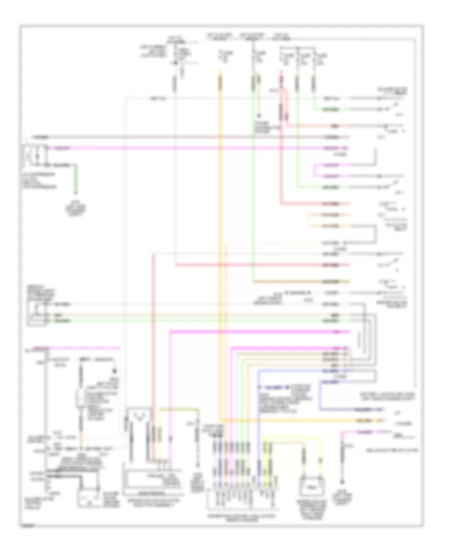
Automatic A/C Wiring Diagram, Except Electric (1 of 2) for Ford Focus SE 2012
List of elements for Automatic A/C Wiring Diagram, Except Electric (1 of 2) for Ford Focus SE 2012:
- (top center of dash) autolamp/ sunload sensor
- Air inlet mode door actuator (right side of dash)
- Aspirator sens
- Auto lamps sens
- Blower control
- Bmrc
- Body control module
- C213
- C2280a
- C2280c
- C2280f
- C228a
- C228b
- Ch123
- Ch201
- Ch202
- Ch203
- Ch204
- Ch205
- Ch206
- Ch207
- Ch208
- Ch209
- Ch210
- Ch211
- Ch212
- Ch213
- Ch214
- Ch215
- Ch227
- Ch228
- Ch229
- Ch230
- Ch231
- Ch237
- Ch238
- Ch239
- Ch240
- Ch241
- Computer data lines system
- Defr a
- Defr b
- Defr c
- Defr d
- Defr pwr
- Defrost mode door actuator (right side of dash)
- Disc floor l sens
- Disc floor r sens
- Disc panel l sens
- Disc panel r sens
- Driver temperature blend door actuator (center of dash)
- Evap temp sens
- Evaporator air discharge temperature sensor (right side of dash)
- Fuse 10a
- Fuse 7.5a
- G201 (bottom of left "a" pillar)
- Gd133
- Gnd
- Hot at all times
- Hot w/ ign relay energized
- Humidity sens
- Hvac module (center of dash)
- In-car sens
- In-vehicle temperature/ humidity sensor (left center of dash)
- L sunl sens
- L temp a
- L temp b
- L temp c
- L temp d
- L temp power
- Left floor discharge air temperature sensor
- Left panel discharge air temperature sensor
- Micro
- Ms can+
- Ms can-
- Pa/fl a
- Pa/fl b
- Pa/fl c
- Pa/fl d
- Pa/fl pwr
- Panel/floor mode door actuator (center of dash)
- R sunl sens
- R temp a
- R temp b
- R temp c
- R temp d
- R temp power
- Recirc a
- Recirc b
- Recirc c
- Recirc d
- Recirc power
- Rh103
- Rh104
- Rh105
- Rh107
- Right floor discharge air temperature sensor
- Right panel discharge air temperature sensor
- S201
- S230 (w/ heated seats)
- S246 (main wiring harness near breakout to passenger temperature blend door actuator)
- Sbp27
- Sens
- Sens gnd
- Sigrtn
- Temperature blend door actuator
- Vbatt
- Vdb06
- Vdb07
- Vh101
- Vh406
- Vh409
- Vh410
- Vh411
- Vh412
- Vh413
- Vh414
- Vh416
- Vh417
- Vln52
- Vpwr
Automatic A/C Wiring Diagram, Except Electric (2 of 2) for Ford Focus SE 2012
List of elements for Automatic A/C Wiring Diagram, Except Electric (2 of 2) for Ford Focus SE 2012:
- (rear of engine compt) a/c pressure transducer
- A/c clutch relay
- A/c compressor clutch field coil (a/c compressor)
- Accr
- Acpt
- Battery junction box (bjb) (left side of engine compt)
- Blower control
- Blower motor (center of dash)
- Blower motor control capacitor (early production) (center of dash)
- Blower motor control module
- Blower motor relay
- C-sigrtn
- C-vref
- C1035c
- C1617j
- C175b
- C175e
- C214
- C297a
- C297b
- Ch109
- Computer data lines system
- Distribution system
- Ect
- Ect-gnd
- Electronics
- Engine coolant temperature (ect) sensor (right rear of engine)
- Engine cooling fan motor (radiator assembly)
- Engine cooling fan relay
- Fan control variable
- Fcv
- Fuse 10a
- Fuse 15a
- Fuse 40a
- Fuse 5a
- G104 (left side of engine compt)
- G105 (left side of engine compt)
- G202 (bottom of right "a" pillar)
- Gd138
- Gnd
- Grille shutter actuator
- High current battery junction box
- Hot at all times
- Hot in start or run
- Hs can+
- Hs can-
- Lh108
- Lin
- Mega fuse 8 50a
- Motor+
- Motor-
- Nca
- Power
- Powertrain control module (pcm) (rear of engine)
- Pwr
- Re141
- Red
- Rh108
- S101
- S102
- S115
- S120 (engine control sensor & fuel charge wiring harness near breakout to c133)
- S203
- S253 (early production) (main wiring harness near breakout to c211)
- Starting/ charging system
- V power
- Vdb04
- Vdb05
- Ve203
- Ve716
- Vh422
- Vpwr
Manual A/C Wiring Diagram, Except Electric (1 of 2) for Ford Focus SE 2012
List of elements for Manual A/C Wiring Diagram, Except Electric (1 of 2) for Ford Focus SE 2012:
- (top center of dash) autolamp/ sunload sensor
- A/c on
- A/c on sw
- Air inlet mode door actuator (right side of dash)
- Auto lamps sens
- Blower motor resistor (right side of dash)
- Blower speed 1
- Blower speed 2
- Blower speed 3
- Blower speed 4
- Bmrc
- Body control module
- C213
- C2280a
- C2280c
- C2280f
- C2357a
- C2357b
- Cbb28
- Cbp04
- Ch123
- Ch201
- Ch202
- Ch203
- Ch204
- Ch205
- Ch207
- Ch208
- Ch232
- Ch233
- Ch234
- Ch235
- Ch236
- Ch427
- Ch428
- Ch429
- Ch434
- Cln17
- Dc recirc+
- Dc recirc-
- Defrost/panel/floor mode door actuator (center of dash)
- Evap temp sens
- Evaporator air discharge temperature sensor (right side of dash)
- Fuse 10a
- Fuse 7.5a
- G201 (bottom of left "a" pillar)
- G202 (bottom of right "a" pillar)
- Gd133
- Gd138
- Gnd
- Hot at all times
- Hot w/ ign relay energized
- Hvac module (center of dash)
- Illum
- Interior lights system
- Micro
- Mode door a
- Mode door b
- Mode door c
- Mode door d
- Mode door power
- Rh107
- S202
- S203
- S230 (w/ heated seats)
- S245 (main wiring harness near breakout to temperature blend door actuator)
- Sbp27
- Sigrtn
- Temp door a
- Temp door b
- Temp door c
- Temp door d
- Temp door power
- Temperature blend door actuator
- Thermal limiter
- V batt
- Vh406
- Vln52
- Vpwr
Manual A/C Wiring Diagram, Except Electric (2 of 2) for Ford Focus SE 2012
List of elements for Manual A/C Wiring Diagram, Except Electric (2 of 2) for Ford Focus SE 2012:
- (center of dash) blower motor
- A/c clutch relay
- A/c compressor clutch field coil (a/c compressor)
- A/c pressure transducer (rear of engine compt)
- Accr
- Acpt
- Battery junction box (bjb) (left side of engine compt)
- Blower motor relay
- C-sigrtn
- C-vref
- C1035c
- C1617j
- C175b
- C175e
- C214
- Ch109
- Computer data lines system
- Ect
- Ect-gnd
- Electronics
- Engine coolant temperature (ect) sensor (right rear of engine)
- Engine cooling fan motor (radiator assembly)
- Engine cooling fan relay
- Fan control variable
- Fcv
- Fuse 10a
- Fuse 15a
- Fuse 40a
- Fuse 5a
- G104 (left side of engine compt)
- G105 (left side of engine compt)
- Gnd
- Grille shutter actuator
- High current battery junction box
- Hot at all times
- Hot in start or run
- Hs can+
- Hs can-
- Lh108
- Lin
- Mega fuse 8 50a
- Nca
- Power distribution system
- Powertrain control module (pcm) (rear of engine)
- Pwr
- Re141
- Red
- Rh108
- S101
- S102
- S115
- S120 (engine control sensor & fuel charge wiring harness near breakout to c133)
- Starting/charging system
- V power
- Vdb04
- Vdb05
- Ve203
- Ve716
- Vh422

 Čeština
 Deutsch
 Ελληνικά
 English
 English
 Español
 Suomi
Suomi Français
 Français
 עברית
עברית Hrvatski
 Magyar
 Italiano
 日本語
日本語 한국어
한국어 Nederlands
 Polski
 Português
 Português
 Română
 Русский
 Slovenčina
 Slovenščina
 Svenska
 Türkçe
 中文 (中国)