POWER DISTRIBUTION
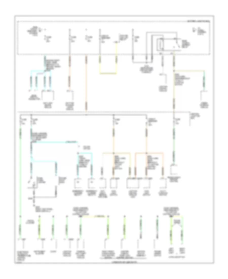
Power Distribution Wiring Diagram (1 of 4) for Ford Crown Victoria 2000


List of elements for Power Distribution Wiring Diagram (1 of 4) for Ford Crown Victoria 2000:
- (dash harn, behind left side of dash) s283
- (dash harness, in breakout to blend door actuator) s245
- (engine compt harn, near breakout to fuse box) s100
- (near breakout to clock) s213
- (rear harn, near breakout to right rear speaker)
- Air suspension compressor motor/ vent solenoid
- Air suspension relay
- Air suspension/ evo steering module
- Base vehicle and police
- Battery
- Battery junction box
- C216
- C251
- C520
- Cd changer
- Circuit breaker 7 20a
- Cooling fan high relay
- Customer use
- Data link connector
- Driver's door module
- Driver's lumbar switch
- Driver's seat control switch
- Except natural gas
- From a fuse 4 (diagram 1 of 4)
- Front control unit
- Fuel pump prime connector
- Fuel pump relay or fuel valve relay
- Fuse 15a
- Fuse 20a
- Fuse 25a
- Fuse 30a
- Fuse 50a
- Generator
- High current relay center
- Horn relay
- Instrument cluster (analog)
- Left rear air spring solenoid
- Master window/ door lock control switch
- Natural gas vehicle module
- Nca
- Passenger's lumbar switch
- Passenger's seat control switch
- Pcm power relay
- Police option
- Police option fuse holder
- Police power relay
- Powertrain control module
- Red
- Relay center
- Right front window/ door lock control switch
- Right rear air spring solenoid
- S114 (right side of engine compartment)
- S124 (engine harn, near breakout to fuel pump prime)
- S144 (engine compt harn, near breakout to fuse box)
- S155
- S282 (dash harn, behind left side of dash)
- S406 (rear harn, near breakout to rear air spring solenoid)
- S411
- Starter/ motor solenoid
- Subwoofer amplifier (lux radio)
- To fuse 14 (diagram 2 of 4)
- To fuse 8 (diagram 1 of 4)
- Trunk lid release switch
- Trunk lid release switch 2
- W/ keyless entry
- W/ power lumbar
- W/o keyless entry
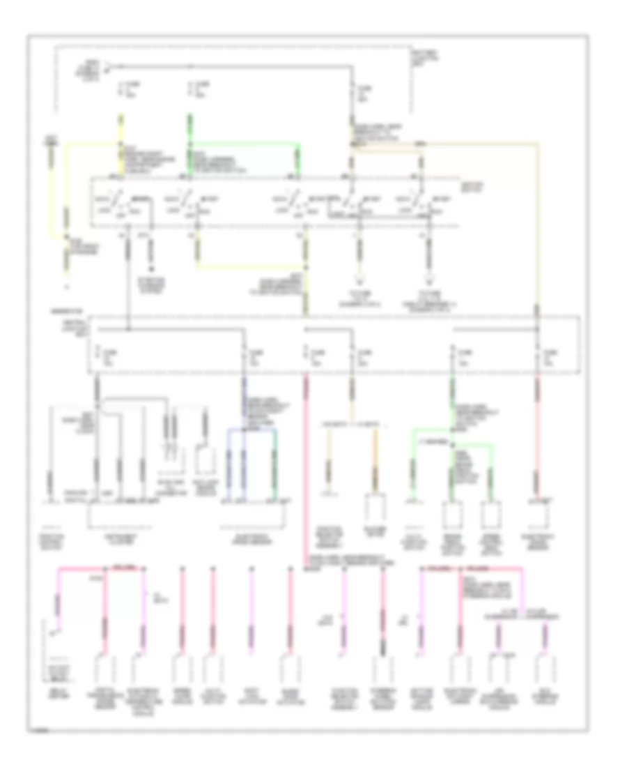
Power Distribution Wiring Diagram (2 of 4) for Ford Crown Victoria 2000
List of elements for Power Distribution Wiring Diagram (2 of 4) for Ford Crown Victoria 2000:
- (dash harness, near breakout to instrument cluster) s294
- (dash harness, near breakout to lighting control module) s227
- (dash harness, near breakout to lighting control module) s228
- (engine compt harn, near breakout to primary crash sensor) s146
- Anti-lock brake module
- Battery junction box
- C2029
- C227
- C249
- C255
- C262
- Central junction box
- Circuit breaker 20a
- Circuit breaker 30a
- Clock
- Cooling fan low relay
- Dash cigar lighter
- Day/ night sensor amplifier
- Daytime running lamps module
- Digital cluster
- Electronic automatic temperature control module
- Emergency flasher relay 1
- Emergency flasher relay 2
- Evac and fill connector
- From circuit breaker 7 (diagram 1 of 4)
- Fuse 10a
- Fuse 15a
- Fuse 20a
- Fuse 40a
- Fuse 50a
- G203 (right kick panel, near door sill)
- Hidden antenna module
- Instrument cluster
- Keypad switch assembly
- Left spot light
- Lighting control module
- Lighting control module (lcm)
- Main light switch
- Master window/ door lock control switch
- Multi- function switch
- Nca
- Passive anti-theft system module
- Police option
- Power mirror switch
- Power point (2000)
- Rear window defrost control
- Rear window defrost relay
- Right front window/door lock control switch
- Right spot light
- S153 (near engine compartment fuse box)
- S206
- S252 (main harn, near breakout to multi- function switch)
- S262 (dash harn, near breakout to lighting control module)
- S285 (dash harn, near breakout to main light switch)
- S426 (trunk harn, near breakout to relay center)
- To fuse 2 (diagram 3 of 4)
- W/police option
- W/remote keyless entry
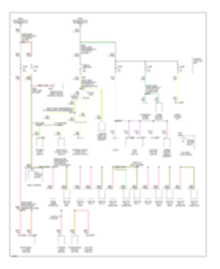
Power Distribution Wiring Diagram (3 of 4) for Ford Crown Victoria 2000
List of elements for Power Distribution Wiring Diagram (3 of 4) for Ford Crown Victoria 2000:
- (analog)
- (dash harn, near breakout to day/night sensor amplifier) s226
- (dash harn, near breakout to day/night/ sensor amplifier) s269
- (dash harn, near breakout to ignition switch) s219
- (dash harn, near breakout to ignition switch) s263
- (digital)
- A/c wot cutout relay
- Acc
- Air suspension/ evo steering module
- Anti-lock brake module
- Battery junction box
- Blend door actuator
- Blower motor
- Brake pedal position switch
- C216
- C251
- C255
- C256
- C277
- Central junction box
- Daytime running lamps module
- Digital transmission range sensor
- Electronic automatic temperature control module
- Electronic crash sensor
- Electronic day/night mirror
- Evac and fill connector
- Evo steering module
- From fuse 14 (diagram 2 of 4)
- Function selector switch assembly
- Fuse 10a
- Fuse 15a
- Fuse 30a
- Fuse 50a
- Generator
- Ignition switch
- Instrument cluster
- Lock
- Multi- function switch
- Nca
- Off
- Relay center
- Run
- S139
- S231 (dash harn, near clock)
- S265 (near brake pedal position switch)
- S272 (dash harness, near breakout to ignition switch)
- S274 (dash harn, near breakout to evo steering module)
- Shift lock actuator
- Speed chime module
- Speed control deac switch
- Start
- Starting/ charging system
- Steering wheel rotation sensor
- To fuse 2, 6, 11 & circuit breaker 14 (diagram 4 of 4)
- To fuse 7 & 13 (diagram 4 of 4)
- Traction control switch
- W/ air suspension
- W/ drl
- W/ eatc
- W/o air suspension
- W/o eatc
Power Distribution Wiring Diagram (4 of 4) for Ford Crown Victoria 2000
List of elements for Power Distribution Wiring Diagram (4 of 4) for Ford Crown Victoria 2000:
- (body harn, near breakout to transmission range sensor) s218
- (dash harn, near breakout to data link connector) s266
- (dash harn, near breakout to ignition switch) s221
- (dash harn, near breakout to trunk lid release switch) s211
- (engine harn, near breakout to camshaft position sensor) s103
- (front of right fender) s151
- Battery junction box
- C2027
- C229
- C232
- C249
- C250
- C251
- C262
- C298
- C520
- Central junction box
- Circuit breaker 20a
- Clock
- Digital cluster
- Driver's door module
- Except police
- From ignition switch (diagram 3 of 4)
- Front control unit
- Fuse 15a
- Fuse 25a
- Fuse 30a
- Fuse 5a
- Ignition coil 1
- Ignition coil 2
- Ignition coil 3 (gasoline)
- Ignition coil 3 (ngv)
- Ignition coil 4 (gasoline)
- Ignition coil 4 (ngv)
- Ignition coil 5 (gasoline)
- Ignition coil 5 (ngv)
- Ignition coil 6 (ngv)
- Ignition coil 7
- Ignition coil 8
- Ignition coil 8 (gasoline)
- Instrument cluster (analog)
- Lighting control module
- Luggage compt lid release switch 1
- Main light switch
- Master window/ door lock control switch
- One touch window down module
- Passive anti- theft system control module
- Pcm power diode
- Police
- Police only
- Police power relay
- Radio noise capacitor
- Relay center
- S2009
- S223 (left side of dash)
- Speed control servo assembly
- Transmission control switch
- W/ keyless entry
- W/o keyless entry
- Warning lamps module
- Windshield wiper motor
- Wiper control module

 Čeština
 Deutsch
 Ελληνικά
 English
 English
 Español
 Suomi
Suomi Français
 Français
 עברית
עברית Hrvatski
 Magyar
 Italiano
 日本語
日本語 한국어
한국어 Nederlands
 Polski
 Português
 Português
 Română
 Русский
 Slovenčina
 Slovenščina
 Svenska
 Türkçe
 中文 (中国)