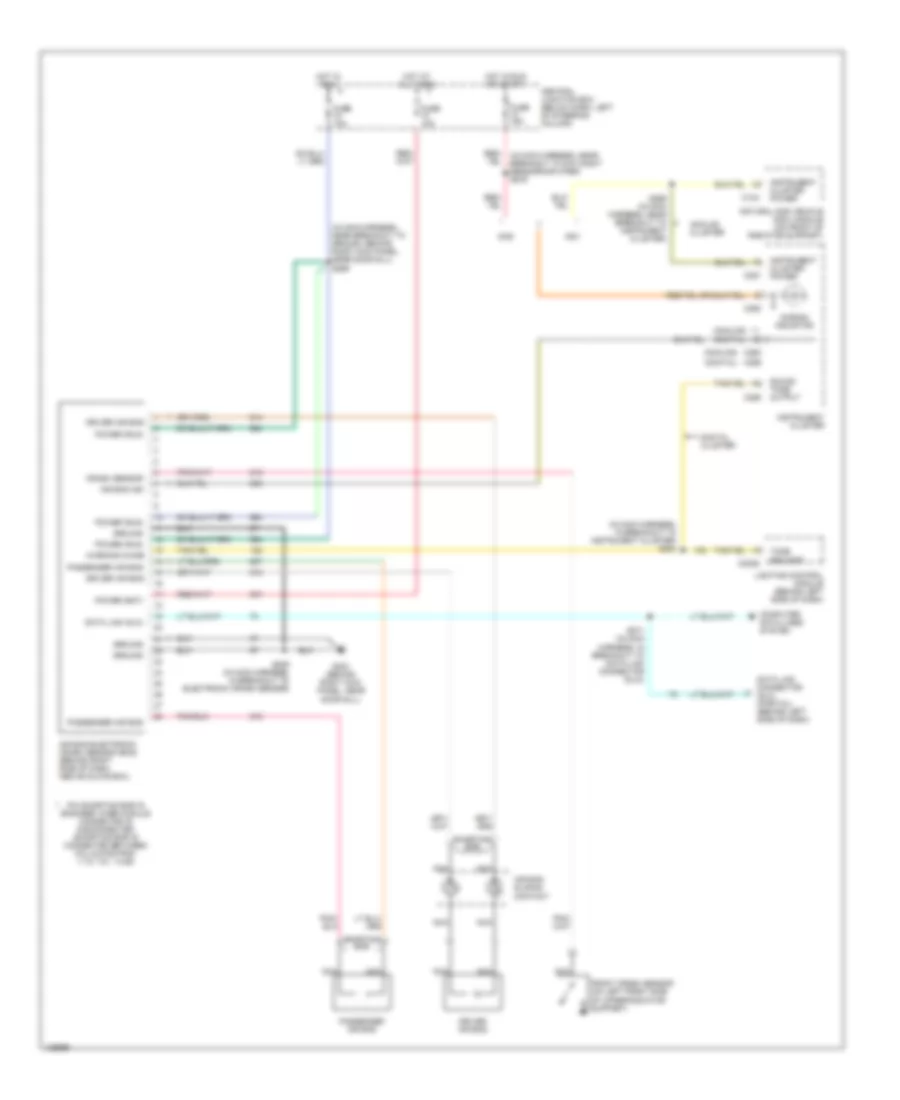
SUPPLEMENTAL RESTRAINTS
Supplemental Restraint Wiring Diagram for Ford Crown Victoria 2000
List of elements for Supplemental Restraint Wiring Diagram for Ford Crown Victoria 2000:
- (analog)
- (analog) (digital)
- (digital)
- (in main harness, in breakout to instrument cluster) s284
- (in main harness, near breakout to ground, behind right kick panel, near door sill) s269
- Air bag electronic crash sensor (ecs) (behind right side of dash, above glove box)
- Air bag ind
- Air bag indicator
- Air bag sliding contact
- Analog cluster
- C124
- C2026
- C250
- C251
- C255
- C256
- Central junction box (below dash, left of steering column)
- Computer data lines system
- Crash sensor
- Data link (dlc)
- Data link connector (dlc) (partial) (behind left side of dash)
- Digital cluster
- Driver air bag
- Front crash sensor (on left front side of upper radiator support)
- Fuse 10a
- Fuse 15a
- G203 (behind right kick panel, near door sill)
- Gas
- Ground
- Hot at all times
- Hot in run
- Hot in run or start
- Instrument cluster
- Instrument cluster power
- Lighting control module (behind left side of dash)
- Natural gas vehicle (ngv) module (on front of radiator support)
- Nca
- Ngv
- Passenger air bag
- Pin shorting bar is engaged when module connector is disconnected (shorting bar is connected between following pins: 1-15, 7-21, 14-28)
- Power (bat)
- Power (run)
- Red/ (in main harness, near breakout to day/night sensor/amplifier) s276
- S209 (in main harness, in breakout to electronic crash sensor)
- S271 (in main harness, in breakout to data link connector (dlc))
- S299 (in main harness, near breakout to instrument cluster)
- Shorting bar
- Sound tone output
- Tone request
- Warning chime
 Čeština
 Deutsch
 Ελληνικά
 English
 English
 Español
 Suomi
Suomi Français
 Français
 עברית
עברית Hrvatski
 Magyar
 Italiano
 日本語
日本語 한국어
한국어 Nederlands
 Polski
 Português
 Português
 Română
 Русский
 Slovenčina
 Slovenščina
 Svenska
 Türkçe
 中文 (中国)
 Dansk
Dansk