
 Čeština
 Deutsch
 Ελληνικά
 English
 English
 Español
 Suomi
Suomi Français
 Français
 עברית
עברית Hrvatski
 Magyar
 Italiano
 日本語
日本語 한국어
한국어 Nederlands
 Polski
 Português
 Português
 Română
 Русский
 Slovenčina
 Slovenščina
 Svenska
 Türkçe
 中文 (中国)

DEFOGGERS
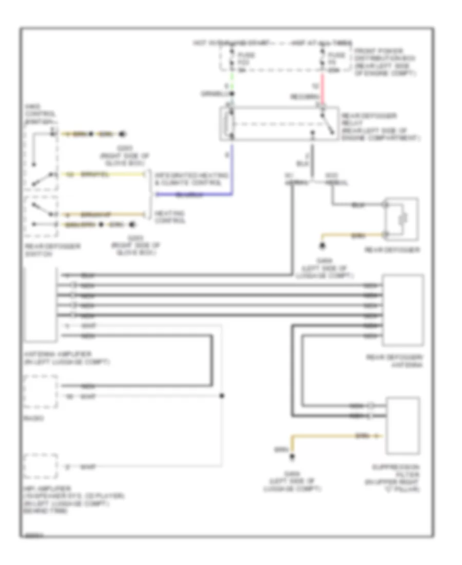
Defogger Wiring Diagram for BMW 318ti 1997
List of elements for Defogger Wiring Diagram for BMW 318ti 1997:

AIR CONDITIONINGBODY COMPUTERANTI-LOCK BRAKESCOMPUTER DATA LINESCRUISE CONTROLDEFOGGERSANTI-THEFTGROUND DISTRIBUTIONENGINE PERFORMANCECOOLING FANEXTERIOR LIGHTSINSTRUMENT CLUSTERINTERIOR LIGHTSPOWER DISTRIBUTIONPOWER SEATSHORNPOWER DOOR LOCKSPOWER WINDOWSPOWER TOP/SUNROOFTRANSMISSIONSHIFT INTERLOCKSWARNING SYSTEMSRADIOPOWER MIRRORSSTARTING/CHARGINGSUPPLEMENTAL RESTRAINTSWIPER/WASHER