ELECTRONIC POWER STEERING
Electronic Power Steering Wiring Diagram for Mitsubishi Lancer GT 2012
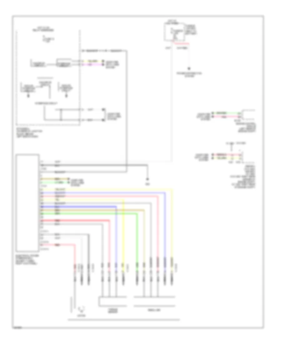
List of elements for Electronic Power Steering Wiring Diagram for Mitsubishi Lancer GT 2012:
- A-03
- A-51
- Abs-ecu (w/o asc) asc-ecu (w/ asc) (w/o asc: right rear corner of engine compt) (w/ asc: right rear of engine compt)
- Analog interface circuit
- B-109
- C-141
- C-141-1
- C-141-2
- C-141-3
- C-141-4
- C-141-5
- C-141-6
- C-141-7
- C140
- Can drive circuit
- Computer data lines system
- Electrical power steering ecu (except turbo: right kick panel)
- Engine control module (left rear of engine compt)
- Etacs-ecu (on rear of junction block, behind left end of dash)
- Fuse 12 7.5a
- Fusible link 80a
- Fusible link box (next to battery)
- G22
- Hot at all times
- Hot w/ ig1 relay energized
- Interface circuit
- Motor
- Nca
- Pnk
- Power distribution system
- Red
- Resolver
- Torque sensor
- W/o asc w/ asc
 Čeština
 Deutsch
 Ελληνικά
 English
 English
 Español
 Suomi
Suomi Français
 Français
 עברית
עברית Hrvatski
 Magyar
 Italiano
 日本語
日本語 한국어
한국어 Nederlands
 Polski
 Português
 Português
 Română
 Русский
 Slovenčina
 Slovenščina
 Svenska
 Türkçe
 中文 (中国)
 Dansk
Dansk