DEFOGGERS
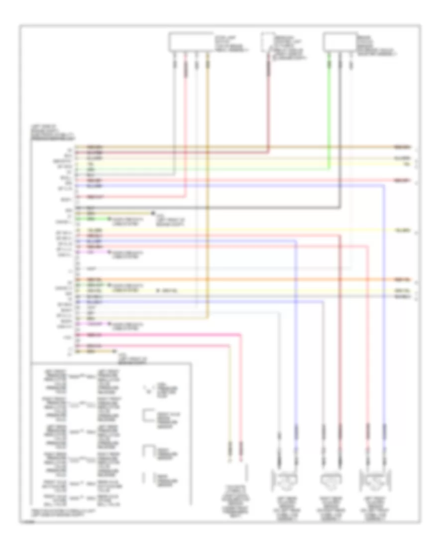
Heated Mirrors Wiring Diagram for Mercedes-Benz C250 2012
List of elements for Heated Mirrors Wiring Diagram for Mercedes-Benz C250 2012:
- (-)
- (left side of engine compt) electronic stability program control unit
- +12v
- 30g
- Bla
- Bls-h
- Bls-m
- Bls-v
- Bls_l
- Brake vacuum sensor (on brake vacuum booster assembly)
- Can e1 h
- Can e1 l
- Can h h
- Can h l
- Computer data lines system
- Df hl (+)
- Df hl s
- Df hr (+)
- Df hr s
- Df vl (+)
- Df vl s
- Df vr (+)
- Df vr s
- Front axle brake pressure sensor
- Front axle intake ball valve
- Front axle switchover valve
- Front pressure sensor
- High pressure & return pump
- Left front axle rpm sensor (on left front wheel hub assembly)
- Left front pressure regulator valve (pressure hold)
- Left front pressure regulator valve (pressure release)
- Left rear axle rpm sensor (on left rear wheel hub assembly)
- Left rear pressure regulator valve (pressure hold)
- Left rear pressure regulator valve (pressure release)
- Nca
- Rear axle intake ball valve
- Rear axle switchover valve
- Rear pressure sensor
- Rear sam control unit w/ fuse & relay module (right side of c9i luggage compt)
- Right front pressure regulator valve (pressure hold)
- Right front pressure regulator valve (pressure release)
- Right rear axle rpm sensor (on right rear wheel hub assembly)
- Right rear pressure regulator valve (pressure hold)
- Right rear pressure regulator valve (pressure release)
- Sig
- Ssk-stat
- Stop lamp switch (top of brake pedal assembly)
- Traction system hydraulic unit (left side of engine compt)
- W70 (left front of engine compt)
- Yaw rate, lateral & longitudinal acceleration sensor (under front passenger's seat)
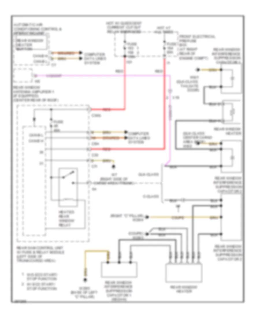
Rear Defogger Wiring Diagram for Mercedes-Benz C250 2012
List of elements for Rear Defogger Wiring Diagram for Mercedes-Benz C250 2012:
- (coupe) w29/3
- (glk-class: center cargo area roof) w8/2
- (right "c" pillar) w29/4
- Automatic air conditioning control & operating unit
- C-class
- C30
- C30g
- C5h
- C7i
- Can-b h
- Can-b l
- Computer data lines system
- Coupe
- Engine compt)
- Front electrical prefuse box (at right rear of
- Fuse 150a
- Fuse 40a
- Fuse 80a
- Glk-class
- Heated rear window relay
- Hot at all times
- Hot w/ quiescent current cutout relay energized
- Ig1
- Rear sam control unit w/ fuse & relay module (left side of trunk/cargo area)
- Rear window antenna amplifier 1 (if equipped) (center rear of roof)
- Rear window heater
- Rear window heater button
- Rear window interference suppression capacitor 1
- Rear window interference suppression capacitor 1 (sedan)
- Rear window interference suppression capacitor 2
- Red
- W/ eco start/ stop function
- W/o eco start/ stop function
- W29/3 (base of left "c" pillar)
- W7 (right side of cargo area/ trunk)
- W8/1 (glk-class: tailgate door)
- X19

 Čeština
 Deutsch
 Ελληνικά
 English
 English
 Español
 Suomi
Suomi Français
 Français
 עברית
עברית Hrvatski
 Magyar
 Italiano
 日本語
日本語 한국어
한국어 Nederlands
 Polski
 Português
 Português
 Română
 Русский
 Slovenčina
 Slovenščina
 Svenska
 Türkçe
 中文 (中国)