POWER DOOR LOCKS
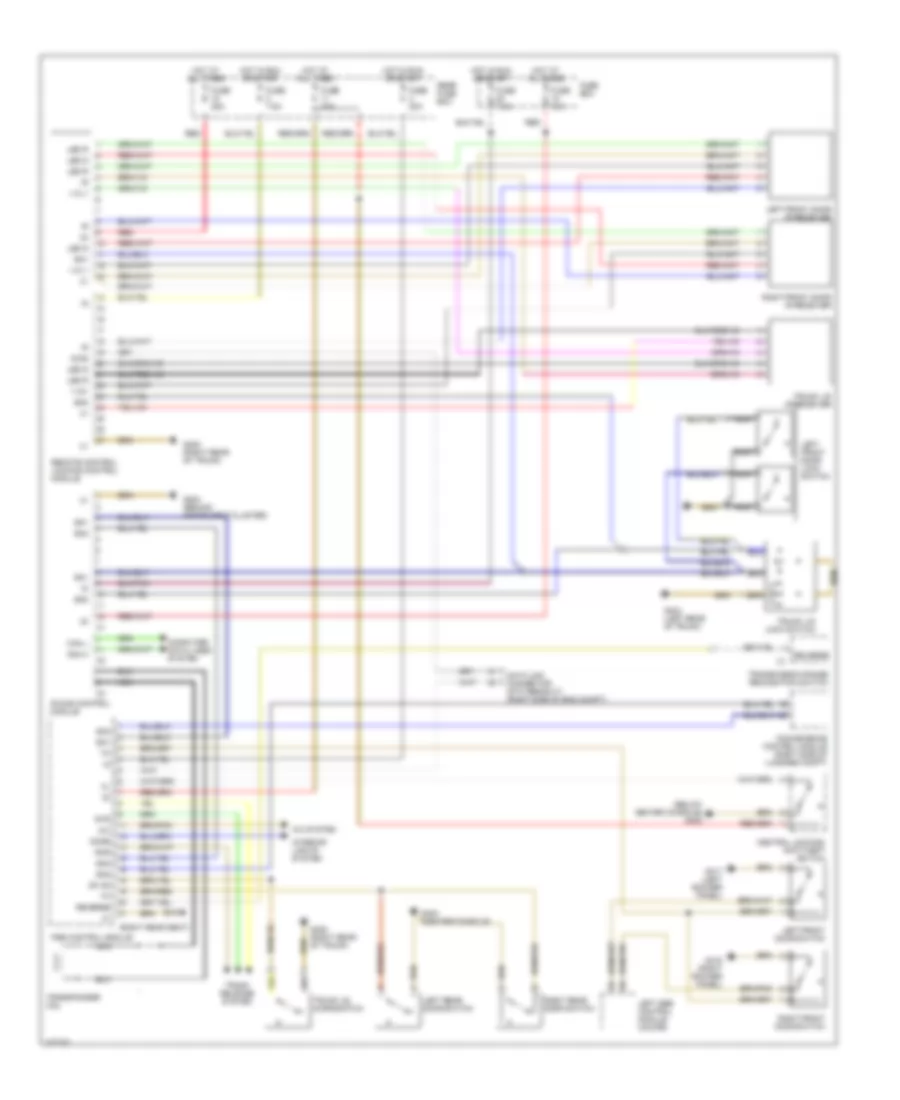
Power Door Lock Wiring Diagram for Mercedes-Benz S500 1997
List of elements for Power Door Lock Wiring Diagram for Mercedes-Benz S500 1997:
- (below center console) g302
- (right rear seat)
- +12 v
- +12v
- A/c
- A/c system
- Can h
- Can l
- Central locking/ anti-theft switch
- Computer data lines system
- Convenience control module (right side of luggage compt)
- Data link connector (dtc readout) (right side of eng compt)
- Df hd
- Diag
- Dome
- Fuse 15a
- Fuse 20a
- Fuse 25a
- Fuse 7.5a
- Fuse box
- G202 (behind instrument cluster)
- G302 (center console)
- G310
- G316 (right rocker panel)
- G317 (left rocker panel)
- G404 (left rear of trunk)
- G405 (right rear of trunk)
- Hot at all times
- Hot in run or start
- Interior lights system
- Ir das control module
- Led g
- Led r
- Left front door ir receiver
- Left front door lock switch
- Left front door switch
- Left rear door switch
- Left sbe control module (coupe)
- Nca
- Pse control module
- Rear fuse box
- Red
- Remote control locking control module
- Reverse
- Rhr
- Right front door ir receiver
- Right front door switch
- Right rear door switch
- Rtr
- Sn1
- Sn2
- Transmission range recognition switch
- Transponder coil
- Trunk lid ir receiver
- Trunk lid lock switch
- Trunk lid microswitch
- Trunk release system
 Čeština
 Deutsch
 Ελληνικά
 English
 English
 Español
 Suomi
Suomi Français
 Français
 עברית
עברית Hrvatski
 Magyar
 Italiano
 日本語
日本語 한국어
한국어 Nederlands
 Polski
 Português
 Português
 Română
 Русский
 Slovenčina
 Slovenščina
 Svenska
 Türkçe
 中文 (中国)
 Dansk
Dansk