AIR CONDITIONING
2.5L
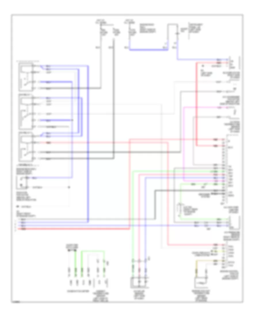
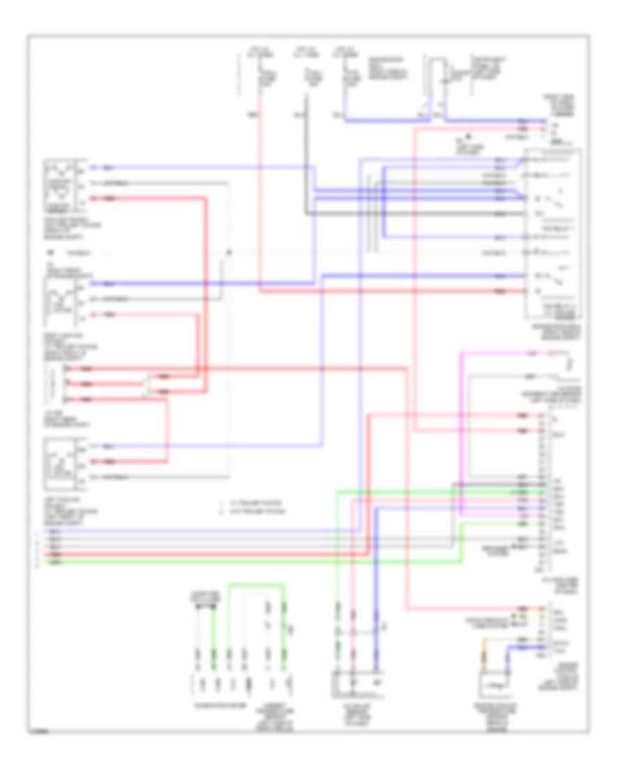
2.5L, Automatic A/C Wiring Diagram (1 of 2) for Toyota RAV4 2011
 https://portal-diagnostov.com/license.html
Automotive Electricians Portal FZCO
Automotive Electricians Portal FZCO
https://portal-diagnostov.com/license.html
https://portal-diagnostov.com/license.html
Automotive Electricians Portal FZCO
Automotive Electricians Portal FZCO
List of elements for 2.5L, Automatic A/C Wiring Diagram (1 of 2) for Toyota RAV4 2011:
- (left side of dash)
- A/c amplifier (center of dash)
- A/c blower assembly
- A/c compressor
- A/c evaporator temperature sensor
- A37
- A41
- A54
- A55
- A70
- A78
- Acc
- Acc fuse 7.5a
- Ae1
- Ae4
- Ae8
- Air inlet damper servo motor
- Air mix driver side damper servo motor
- Air mix front passenger's side damper servo motor
- Air vent mode damper servo motor
- B bus
- B1 (rear of engine)
- B13
- B24
- B30
- B31
- B33
- B39
- B40
- B46
- B66
- B68
- B69
- B70
- Ba1
- Ba3
- Bus
- Bus g
- Canh
- Canl
- Color (green) connector housing
- Computer data lines system
- Connector housing color (black)
- Connector housing color (red)
- E1 (left kick panel)
- E17
- E23
- E3 (left side of dash)
- E37
- E91
- Ecu-b fuse 10a
- Ecu-b2 fuse 7.5a
- Ecu-ig1 fuse 10a
- Ecu-ig2 fuse 10a
- Engine room r/b 2 (right side of engine compt)
- Floq
- Gnd
- H12
- Hot at all times
- Hot in on or acc
- Hot in on or start
- Ig+
- Instrument panel j/b (left side of dash)
- Integration control & panel assembly
- J/b 3
- J/b 4 (center of dash)
- J/c a37
- Lin1
- Pre
- Qufl
- Red
- S5-1
- S5fl
- Sg-4
- Sga
- Sgfl
- Sol+
- Sol-
- Tea
- Tmc made
- Tmmc made
- W/ pulley compressor assembly
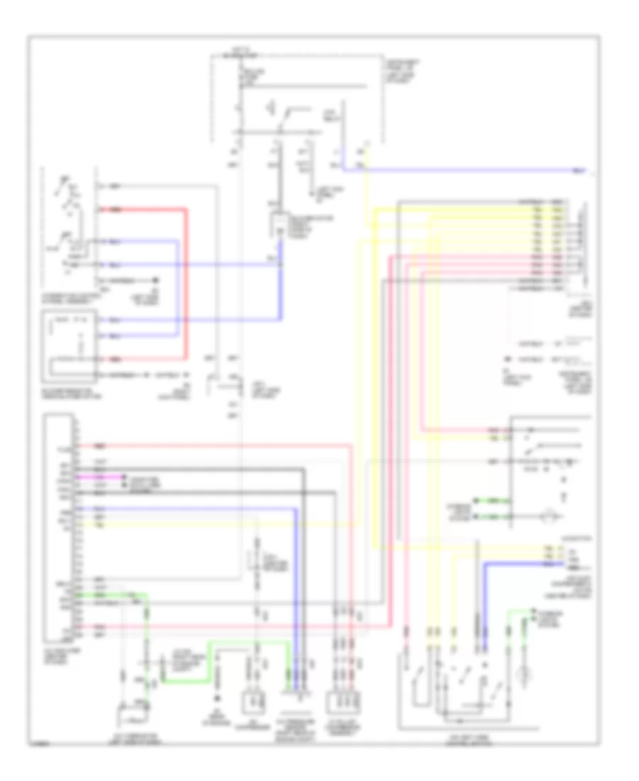
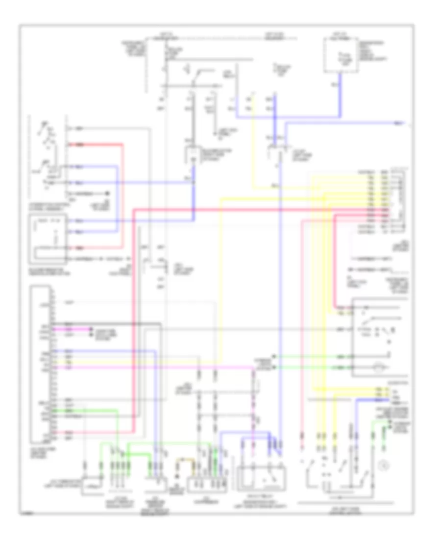
2.5L, Automatic A/C Wiring Diagram (2 of 2) for Toyota RAV4 2011
List of elements for 2.5L, Automatic A/C Wiring Diagram (2 of 2) for Toyota RAV4 2011:
- A/c amplifier (center of dash)
- A/c condenser fan motor (behind left side of radiator)
- A/c pressure sensor (right rear of engine compt)
- A/c room temperature sensor (left side of dash)
- A/c solar sensor (left side of dash)
- A3 (right front of engine compt)
- Ae6
- Ae7
- Ambient temperature sensor (left side of front grille)
- B30
- Blower motor (right side of dash)
- Blw
- Canh
- Canl
- Cds fuse 30a
- Combination meter
- Computer data lines system
- Defogger system
- E3 (left side of dash)
- E37
- Ef1
- Engine control module (left side of engine compt)
- Engine coolant temperature sensor (left rear of engine)
- Engine room r/b 2 (right side of engine compt)
- Ethw
- Fan relay 1
- Fan relay 2
- Fan relay 3
- Fanh
- Fanl
- Gnd
- Hot at all times
- Htr fuse 50a
- Instrument panel j/b (left side of dash)
- J/c a40 (right rear of engine compt)
- Lin1
- Ot+
- Ot-
- Pnk
- Radiator fan motor (behind left side of radiator)
- Rdfg
- Rdi fuse 30a
- Red
- S5-3
- S5-4
- Sg-1
- Sg-2
- Short pin
- Temp
- Thw
- Tsd
- Tsp
- Tx1+
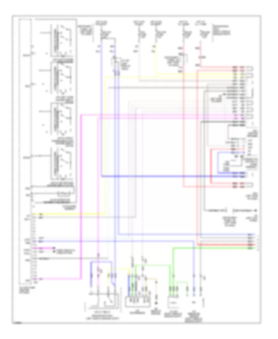
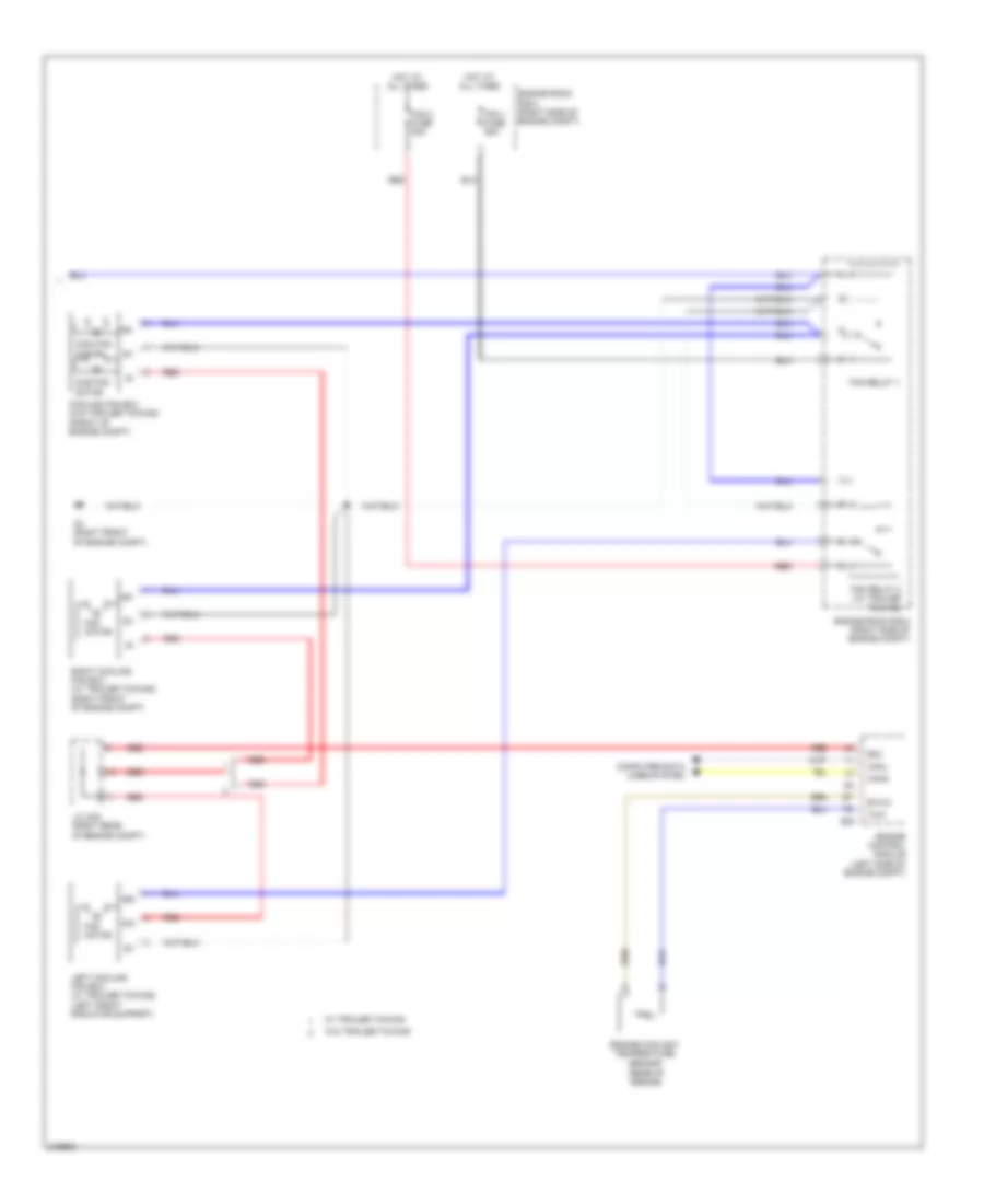
2.5L, Manual A/C Wiring Diagram (1 of 2) for Toyota RAV4 2011
List of elements for 2.5L, Manual A/C Wiring Diagram (1 of 2) for Toyota RAV4 2011:
- (left kick panel)
- (left kick panel) e1
- (left side of dash)
- A/c
- A/c amplifier (center of dash)
- A/c compressor
- A/c pressure sensor (right rear of engine compt)
- A/c switch
- A/c thermistor (left side of dash)
- A31
- A38
- A39
- A40
- A41
- A42
- A43
- A44
- A45
- A55
- A78
- Ae1
- Ae4
- Ae7
- Air inlet damper servo motor (center of dash)
- Air vent mode control switch
- B1 (rear of engine)
- B31
- B35
- Ba1
- Ba3
- Blower motor (right side of dash)
- Blower resistor (near blower motor)
- Canh
- Canl
- Computer data lines system
- E17
- E24
- E3 (left side of dash)
- E4 (right kick panel)
- Ecu-ig2 fuse 10a
- Floq
- Frs
- Gnd
- Hot in on or start
- Htr relay
- Ig+
- Instrument panel j/b
- Integration control & panel assembly
- Interior lights system
- J/b 3 (left side of dash)
- J/b 4 (center of dash)
- J/c a40 (right rear of engine compt)
- Led
- Off
- Pnk
- Pre
- Qufl
- Rec
- Red
- S5-1
- S5-3
- S5fl
- Sblw
- Sg-2
- Sg-3
- Sgfl
- Sol+
- Sol-
- W/ pulley compressor assembly
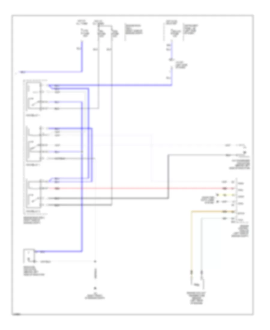
2.5L, Manual A/C Wiring Diagram (2 of 2) for Toyota RAV4 2011
List of elements for 2.5L, Manual A/C Wiring Diagram (2 of 2) for Toyota RAV4 2011:
- A/c condenser fan motor (behind left side of radiator)
- A3 (right front of engine compt)
- B24
- B30
- Canh
- Canl
- Cds fuse 30a
- Computer data lines system
- Ecu-ig1 fuse 10a
- Engine control module (left side of engine compt)
- Engine coolant temperature sensor (left rear of engine)
- Engine room r/b 2 (right side of engine compt)
- Ethw
- Fan relay 1
- Fan relay 3
- Fanh
- Fanl
- Hot at all times
- Hot in on or start
- Htr fuse 50a
- Instrument panel j/b (left side of dash)
- J/c a37 (left side of dash)
- Radiator fan motor (behind left side of radiator)
- Rdi fuse 30a
- Red
- Thw
3.5L
3.5L, Automatic A/C Wiring Diagram (1 of 2) for Toyota RAV4 2011
List of elements for 3.5L, Automatic A/C Wiring Diagram (1 of 2) for Toyota RAV4 2011:
- (left side of dash)
- A/c amplifier (center of dash)
- A/c blower assembly
- A/c compressor
- A/c evaporator temperature sensor
- A/c pressure sensor (right rear of engine compt)
- A37
- A41
- A50
- A51
- A54
- A55
- A70
- A78
- Acc
- Acc fuse 7.5a
- Ae4
- Ae7
- Ae8
- Air inlet damper servo motor
- Air mix driver side damper servo motor
- Air mix front passenger's side damper servo motor
- Air vent mode damper servo motor
- B bus
- B13
- B23
- B24
- B3 (rear of engine)
- B30
- B31
- B33
- B39
- B40
- B46
- B47
- B66
- B68
- B69
- B70
- Ba1
- Ba3
- Bus
- Bus g
- Canh
- Canl
- Color (green) connector housing
- Computer data lines system
- Connector housing color (black)
- Connector housing color (red)
- E1 (left kick panel)
- E17
- E23
- E3 (left side of dash)
- E37
- E91
- Ecu-b fuse 10a
- Ecu-b2 fuse 7.5a
- Ecu-ig1 fuse 10a
- Ecu-ig2 fuse 10a
- Engine room r/b 1 (left side of engine compt)
- Engine room r/b 2 (right side of engine compt)
- Gnd
- H12
- Hot at all times
- Hot in on or acc
- Hot in on or start
- Ig+
- Instrument panel j/b (left side of dash)
- Integration control & panel assembly
- J/b 3 (left side of dash)
- J/b 4 (center of dash)
- J/c a37
- J/c a40 (right rear of engine compt)
- Lin1
- Lock
- Mg clt relay
- Mg+
- Mgc
- Pre
- Red
- Sga
- Sol+
- Sol-
- Ssr+
- Ssr-
- Tea
- Tmc made
- Tmmc made
3.5L, Automatic A/C Wiring Diagram (2 of 2) for Toyota RAV4 2011
List of elements for 3.5L, Automatic A/C Wiring Diagram (2 of 2) for Toyota RAV4 2011:
- (rear of engine)
- (right side of dash) blower motor
- +b1
- +b2
- A/c amplifier (center of dash)
- A/c room temperature sensor (left side of dash)
- A/c solar sensor (left side of dash)
- A3 (right front of engine compt)
- Ae6
- Ambient temperature sensor (left side of front grille)
- B30
- Blw
- Canh
- Canl
- Combination meter
- Computer data lines system
- Cooling fan ecu (w/o trailer towing) (front of engine compt)
- Defogger system
- E3 (left side of dash)
- E37
- Ef1
- Engine control module (left side of engine compt)
- Engine coolant temperature sensor
- Engine room r/b 2 (right side of engine compt)
- Ethw
- Fan 1 fuse 50a
- Fan 2 fuse 50a
- Fan motor
- Fan relay 1
- Fan relay 2 (w/ trailer towing)
- Gnd
- Hot at all times
- Htr fuse 50a
- Instrument panel j/b (left side of dash)
- J/c a39 (right rear of engine compt)
- Left cooling fan ecu (w/ trailer towing) (left front of engine compt)
- Lin1
- Main fan motor
- Ot+
- Ot-
- Pnk
- Rdfg
- Red
- Rfc
- Right cooling fan ecu (w/ trailer towing) (right front of engine compt)
- S5-3
- S5-4
- Sg-1
- Sg-2
- Short pin
- Si2
- Sub fan motor
- Temp
- Thw
- Tsd
- Tsp
- Tx1+
- W/ trailer towing
- W/o trailer towing
3.5L, Manual A/C Wiring Diagram (1 of 2) for Toyota RAV4 2011
List of elements for 3.5L, Manual A/C Wiring Diagram (1 of 2) for Toyota RAV4 2011:
- (left kick panel) e1
- (left side of engine compt)
- A/c
- A/c amplifier (center of dash)
- A/c compressor
- A/c pressure sensor (right rear of engine compt)
- A/c switch
- A/c thermistor (left side of dash)
- A31
- A38
- A39
- A40
- A41
- A42
- A43
- A44
- A45
- A50
- A51
- A55
- A78
- Ae4
- Ae7
- Air inlet damper servo motor (center of dash)
- Air vent mode control switch
- B23
- B24
- B3 (rear of engine)
- B31
- B35
- B47
- Ba1
- Ba3
- Blower motor (right side of dash)
- Blower resistor (near blower motor)
- Canh
- Canl
- Computer data lines system
- E1 (left kick panel)
- E17
- E24
- E3 (left side of dash)
- E4 (right kick panel)
- Ecu-ig1 fuse 10a
- Ecu-ig2 fuse 10a
- Engine room r/b 1
- Engine room r/b 2 (right side of engine compt)
- Frs
- Gnd
- Hot at all times
- Hot in on or start
- Htr fuse 50a
- Htr relay
- Ig+
- Instrument panel j/b (left side of dash)
- Integration control & panel assembly
- Interior lights system
- J/b 3 (left side of dash)
- J/b 4 (center of dash)
- J/c a37 (left side of dash)
- J/c a40 (right rear of engine compt)
- Led
- Lock
- Mg clt relay
- Mg+
- Mgc
- Off
- Pnk
- Pre
- Rec
- Red
- S5-3
- Sblw
- Sg-2
- Sol+
- Sol-
- Ssr+
- Ssr-
3.5L, Manual A/C Wiring Diagram (2 of 2) for Toyota RAV4 2011
List of elements for 3.5L, Manual A/C Wiring Diagram (2 of 2) for Toyota RAV4 2011:
- (rear of engine)
- +b1
- +b2
- A3 (right front of engine compt)
- B30
- Canh
- Canl
- Computer data lines system
- Cooling fan ecu (w/o trailer towing) (front of engine compt)
- Engine control module (left side of engine compt)
- Engine coolant temperature sensor
- Engine room r/b 2 (right side of engine compt)
- Ethw
- Fan 1 fuse 50a
- Fan 2 fuse 50a
- Fan motor
- Fan relay 1
- Fan relay 2 (w/ trailer towing)
- Hot at all times
- J/c a39 (right rear of engine compt)
- Left cooling fan ecu (w/ trailer towing) (left front radiator support)
- Main fan motor
- Red
- Rfc
- Right cooling fan ecu (w/ trailer towing) (right front of engine compt)
- Si2
- Sub fan motor
- Thw
- W/ trailer towing
- W/o trailer towing

 Čeština
 Deutsch
 Ελληνικά
 English
 English
 Español
 Suomi
Suomi Français
 Français
 עברית
עברית Hrvatski
 Magyar
 Italiano
 日本語
日本語 한국어
한국어 Nederlands
 Polski
 Português
 Português
 Română
 Русский
 Slovenčina
 Slovenščina
 Svenska
 Türkçe
 中文 (中国)